 |
|
 |
| A variant has the N5875 handset |
|
B variant has the N5885B handset |
Click here for an article on the N1014
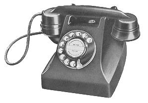
Standard Automatic or CB
desk instrument
Introduced around 1951 and known as the 1000 type.
Available in Black, Ivory, Chinese Red, Jade Green
or
Mother of Pearl (Supplied to the Royal Palace, Baghdad).
This is our latest automatic telephone and is alternative to the N1002
type instrument, the efficiency of which has made it so popular. The new set gives equally
satisfactory service and includes the same types of components in a redesigned case having
rounded contours of aesthetically pleasing shape.
The design of the cradle and the plunger mechanism ensures smooth, reliable operation,
whilst the handset and automatic dial, being standard B.P.O. type, are of proved
efficiency. Later models were fitted with the N5875 style handset from about 1955 onwards.
Alternative marking can be provided on the dial label and number plate to suit customers'
requirements.
The internal components, comprising induction coil, capacitors, ringer, cradle switch,
and screw-terminal blocks for connecting the dial and desk cords, are mounted on a metal
base-plate attached to the case by four captive screws. The equipment is thus removable as
a unit and is thereby very accessible for maintenance. Perforations in the base plate
ensure audibility of the ringing signals.
A diagram of the connections is fixed inside the case.
The line wires are attached to screw terminals in a moulded Bakelite case connected to
the telephone by a flexible cord.
All the components are of standard, proved type with finishes suitable for temperate or
tropical conditions, as specified on the order.
|
Code No. |
Type |
Weight |
Information found in Catalogue No. |
|
N1014 |
Auto |
4.75 lb |
A variant - Catalogue 49 |
|
N1373 |
CB |
4.5 lb. |
A variant - Catalogue 49 and B variant - Catalogue 55 |
Note:- This instrument is not designed to accommodate a directory tray.
The N1373 was an N1014 without the dial but fitted instead with a Dummy plate
N19155T. The dial terminals 4 and 5 were also linked together.
Dimensions: 9.25 x 7.5 x 5.5 inches.
Taken from the Ericsson (ETL) Telephone Catalogue No. 49
N1014 variants
N1014 - Introduced around 1951.
N1014A6T - Used on party line working on Automatic or CB exchanges. Fitted
with a Thermistor.
N1014A1T - Standard telephone - CB or Automatic.
N1014B1T - This was used on separate lines or party lines. It has
two terminal blocks, one of which has terminals prefixed by the letter "A".
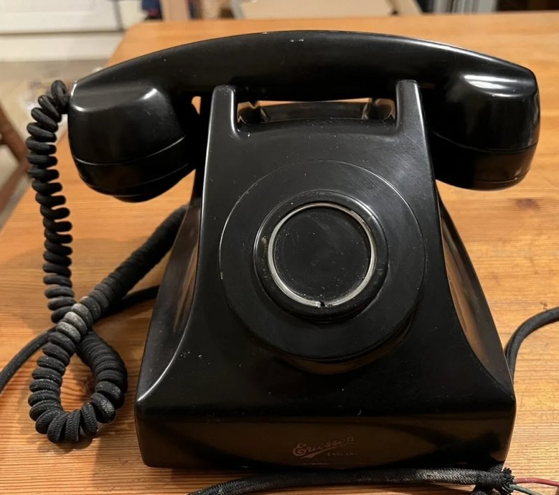
N1014B20F2 - Pearl cased variant. The picture below has the inscription
"presented to R. E. German Esq. CMG on the occasion of the inauguration of the new
Mombasa automatic telephone system 27th November 1954".
N1014B44T - Used as a main phone. This model has two terminal blocks,
one of which has terminals prefixed by the letter "A". CB and Auto
variants.
N1014B53T - Basic telephone in black.
N1014B55T - Basic telephone in black.
N1014B68T - Basic telephone in black supplied to Telephone Rentals.
N1014B78FT - Automatic table telephone, ivory colour, dial type with woven
covered flex. Some carry a transfer of the coat of arms of the Royal
Palace of Baghdad, Iraq, for whom this model was designed. It also has
Arabic numerals on the dial and marked "EST" on the receiver.
N1014B96T - Basic telephone.
N1014B99T - Was supplied in Ivory to Hull Corporation.
These phones can be dated by reference to the markings on the capacitor e.g.
C59/2 would be made by GEC in 1959.

Mother of Pearl

N1014B68T - Side view (the dial label is incorrect)

N1014B68T - Base

N1014B68T - Components
N1014A1T (CB variant)
How to convert a N1014 to plug and socket
These conversions assume that you are discarding the original line cord.
Model N1014A1T (diagram N77339 dated 1951)
- Connect white of line cord to Terminal 1.
- Connect a 3.3k resistor across Terminals 1 and 2.
- Disconnect the red/orange wire from the 2uf capacitor and connect to the
blue wire of the line cord.
- Connect the red wire of the line cord to terminal 3.
- Connect a Rectifier Element No. 205 across Terminals 4 and 5.
- The green wire of the wire cord is not used and should be insulated with
a piece of insulating tape.
Model N1014A6T (diagram N79693 dated 1953)
- Conversion details on request.
Model N1014B20, N1014B57FT and N1014B68T (diagram N84247 dated 1954)
- Connect white of new line cord to Terminal 1.
- Connect a 3.3k resistor across Terminals 1 and 2.
- Disconnect the red/orange wire from the 2uf capacitor and connect to the
blue wire of the new line cord.
- Connect the red wire of the new line cord to Terminal 3.
- Connect a Rectifier Element No. 205 across Terminals 4 and 5.
- The green wire of the new wire cord is not used and should be insulated with
a piece of insulating tape.
Model N1014B1T (diagram N80978 dated 1953)
- Connect white of line cord to Terminal A6.
- Connect a 3.3k resistor across Terminals A6 and A3.
- Remove the Red/Orange wire from the capacitor and insulate the bare end.
- Connect the blue wire of the line cord to Terminal A2.
- Remove any wire on Terminal A1.
- Connect Terminals A2 and A5 together.
- Connect the red wire of the line cord to Terminal A4.
- Connect a Rectifier Element No. 205 across Terminals 4 and 5.
- The green wire of the wire cord is not used and should be insulated with
a piece of insulating tape.
Model N1014B44T (diagram N84975 dated 1955)
- Connect white of line cord to Terminal A6.
- Connect a 3.3k resistor across Terminals A6 and A3.
- Connect Terminal 3 to A4 together.
- Connect Terminals A1 and A2 together.
- Connect the blue wire of the line cord to Terminal A2.
- Connect the red wire of the line cord to Terminal A4.
- Connect a Rectifier Element No. 205 across Terminals 4 and 5.
- The green wire of the wire cord is not used and should be insulated with
a piece of insulating tape.
|
 ERICSSON TELEPHONE
