| |||||||||||||||||||||||||||||||||||||||||||||||||||||
| Magneto Floor Switchboards Cordless
N563 shown pictured to the right. Enamelled cast-iron stand, matt polished woodwork with fibre-faced jack field. The connections are made by means of cordless plugs, and the jacks are mounted in rows varying in number, according to the size of the switchboard. Each row, parallel with the line indicators, represents a connecting circuit and has associated a clearing indicator, an operating key and two plugs. A key, connected to the generator, is fitted in each line circuit for calling purposes.
Night bell, switch, micro-telephone, testing key and two spare plugs are provided.
N560 and N561 have the connecting circuits arranged vertically. N564 is replaced by N569 Taken from the Ericsson catalogue, edition 26 INTRINSICALLY SAFE SWITCHBOARDS
The sloping top of the case is reinforced by a steel plate which projects over the front and affords protection against falling roof material and water. Steel mounting bars are fitted, but to ensure free circulation of air at the back and thus reduce the risk of corrosion by moisture, the board should be mounted on battens. On the hinged front plate are mounted six push-button-restored, totally enclosed disc indicators and the push keys, which have stout metal tops and plungers. The front plate is fastened at the top by special screws for which a key is supplied. One of the push keys is used for switching in an external bell and battery, both of which should be of approved type and ordered separately. The connecting keys have their tops engraved to indicate the lines which are connected together when the keys are pressed. A separate intrinsically safe telephone is required for the operator. When an indicator is actuated, the operator presses the associated key in the bottom row and asks for the number required, then operates the appropriate connecting key and the telephone generator to ring out. On receiving a reply, the operator releases the bottom key and presses the indicator button so that a 'ring off' signal can be received at the end of the call. The line cable enters via a gland in the bottom of the board and connects to screw terminals on strips mounted on the rear wall. The gland normally supplied is for s.w.a. cable. If a different gland is required the type and overall diameter of the cable must be specified. If cable is in conduit, the latter can be held in position by nuts. Terminals are included in lines 1 to 3 for the connection of a Type N8656 Code Ringing Delay Unit which permits code ringing between stations on the same line without the indicator being actuated. Circuit schematic and wiring diagrams are supplied with each board. All connecting wires are insulated with p.v.c.
Taken from the Ericsson Catalogue No. 60 |
|||||||||||||||||||||||||||||||||||||||||||||||||||||
Last revised: November 24, 2025FM2 |
 ERICSSON
 These switchboards are designed for use where larger ultimate capacity than the Pyramid
type, previously described, is required. They are arranged to give a limited number of
connections in order that the overall dimensions are not unduly large.
These switchboards are designed for use where larger ultimate capacity than the Pyramid
type, previously described, is required. They are arranged to give a limited number of
connections in order that the overall dimensions are not unduly large.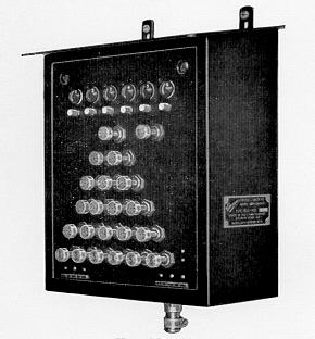 This is a black-finished all-steel switchboard much favoured in the coal
mining and petroleum industries because it is simple to operate, requires very little
maintenance and will withstand hard usage. It is known as the 'pyramid' type on account of
the formation of the keys.
This is a black-finished all-steel switchboard much favoured in the coal
mining and petroleum industries because it is simple to operate, requires very little
maintenance and will withstand hard usage. It is known as the 'pyramid' type on account of
the formation of the keys.