 L. M.
ERICSSON L. M.
ERICSSONSWITCHBOARD OB 1300, OB 1301 & OB 1302 | ||||||
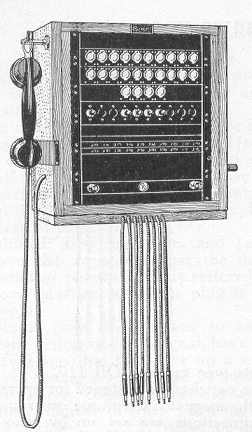
| TYPE OB 1300, OB 1301 and OB 1302 SWITCHBOARDS FOR LB SYSTEMS OB 1300 The OB 1300 was renumbered, circa 1939, by the ABH 13. The switches are fitted with speaking and ringing devices. Connections are set up by means of cords and keys. The switches are made for 10, 20 and 30 lines with 3, 4 or 6 cords depending on model ordered. Type OB 1300/20/4 shown pictured.
It is made also for 40 and 50 lines. Type OB 1301/30/6 shown pictured. The OB 1301 was renumbered, circa 1939, by the ABH 14 and was made for
20, 30, 40 and 50 lines.
Type OB 1302/30/6 shown pictured. The OB 1302 was renumbered, circa 1939, by the ABH 15 and was made for
20, 30, 40 and 50 lines. General The cords are made in two colours: red and grey. Odd cord circuits have red cords and even cord circuits have grey cords. The microtelephones are our modern Bakelite type. The generators have 5 magnets. All conductive parts are fitted on insulating material of high quality. Electric properties. The parts belonging to 10 lines, consisting of 10 calling signals and 10 jacks with terminal strip are joined to a separate lines group set. The necessary parts for one speaking circuit, consisting of one cord circuit with accessories, key, clearing indicator, and terminal base, are joined to a separate switching set. The parts are simple to fit in the switchboards, which makes extensions very simply to carry out. This, however, does not refer to the smaller types of wall switches which cannot be extended. All switchboards are fitted with terminals for the lines and consequently the lines are in no case connected direct to the jacks. Batteries are supplied only on special request. They can be made up of dry cells or storage batteries. The tension of the microphone battery should be 4.5 Volts for all switchboards. The tension of the signalling battery for wall switches and switchboards with drop indicators, combined drop indicators and jacks or indicator jacks should be 4.5 Volts, and for switchboards with visual indicators and all multiple switchboards it should be 6 Volts.
|
||||||
Last revised: March 30, 2024FM2 |
 This
type replaces the OB 750.
This
type replaces the OB 750. This
type is similar to OB 1300 but has a larger frame.
This
type is similar to OB 1300 but has a larger frame.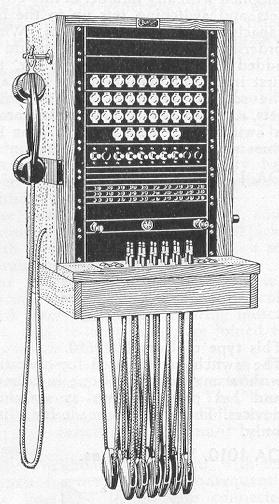 This
type is similar to OB 1301 but is fitted with cord weights and plug board.
This
type is similar to OB 1301 but is fitted with cord weights and plug board.