Introduced around 1963
Made by Ericsson (ETL)
HES 3 diagram (ZIP)
HES 3 circuit diagrams (PDF)
Descriptive Leaflet - 1965
Descriptive Leaflet - 1980
Q Diagrams
Document list
Circuit Diagrams
Multiple stations only - SA9174.
Multiple stations with Non-Multiple extension - SA9175.
TELECOMMUNICATIONS INSTRUCTION
C MARKETING
INSTALLATION
3 Internal
C3030
Issue 2, Aug 1973
THE HOUSE EXCHANGE SYSTEM
No. 3
Facilities
1 GENERAL
This Instruction describes the facilities provided in a House Exchange System No. 3 (HES No. 3) which has been given the sales name of 'Keymaster'. This system provides intercommunication between a maximum of five stations with direct access from these stations to an exchange line.
2 DEFINITIONS -
Multiple station A multiple station is one equipped with a Telephone, Intercom No. 3/1 (F or CB) which is a 700 type instrument. Multiple stations are linked by multiple cable and are normally confined to one building but the multiple may be extended to link stations in a nearby building if signalling limits are not exceeded. -
Non-multiple extension This is an extension station which is equipped with a Telephone No. 710 (F or CB); it is connected to the multiple by a two-wire line and a relay-unit. -
Main station This is the multiple station where incoming exchange calls always give an audible signal, and which assists the non-multiple extension with calls to other stations. The main station also controls soon of the additional facilities which may be added to the system.
3 CAPACITY OF INSTALLATION
A HES No. 3 comprises one exchange line and up to five stations. One non-multiple extension may be connected in place of the last multiple station, and stations may also be replaced by private circuits to another house exchange system or a PBX. The system also includes one or two relay-units and a Power-unit No. 51A; all these units are wall-mounted.
4 EXCHANGE CALLS
 The HES No. 3 works on CB principles but may be connected to any type of public exchange. In LB areas an auxiliary unit must be fitted at the exchange to provide the required CB conditions. The HES No. 3 works on CB principles but may be connected to any type of public exchange. In LB areas an auxiliary unit must be fitted at the exchange to provide the required CB conditions.
The HES No. 3 is unsuitable for shared service.
Exchange service is available from any station including the non-multiple extension. Access to the exchange line is by a locking press-button with gravity switch restoration. Exchange calls are secret. Calls may be held by any station and transferred to any other station.
Incoming exchange calls normally ring a standard magneto bell mounted inside the Telephone, Intercom No. 3/1 at each multiple station but they do not ring a bell at the non-multiple extension except for night service. Each Telephone, Intercom No. 3/1 is fitted with a bell cut-off key. This key is made inoperative at the main station to ensure that at least one bell of the installation can be rung by incoming exchange calls. If the exchange ringing supply is sub-standard, e.g. from a vibrator, it may not be possible to ring all bells simultaneously and one or two may have to be permanently short-circuited.
5 INTERCOM CALLS
A multiple station can call any other station by means of a non-locking press-button. The non-multiple extension cannot call multiple stations directly and relies on the main station to signal the required station.
Buzzer tone is returned to the non-multiple extension as an indication that the main station is being called. Intercom calls are signalled at multiple stations by buzzer and at the non-multiple extension by magneto bell.
The intercom speech circuit is common to all stations, thus intercom calls are not secret. At multiple stations automatic connection to the intercom circuit is made when the handset is lifted but at the non-multiple extension the EXTN button must also be pressed. 6 CONFERENCE CALLS
All stations can be called in to a local conference by signalling each in turn. Conference facilities are not available on exchange calls.
7 LAMP SIGNALS
Telephones, Intercom No. 3/1 are fitted with two MES bulbs. A red lamp signal indicates that the exchange line is engaged and warns other stations not to operate the exchange button as this interrupts the exchange line circuit. This lamp glows in rhythm with the ringing current on incoming exchange calls but is not intended to be a general calling signal. This lamp also flickers when an exchange call is held, e.g. while arranging for the transfer of the call to another station.
A white lamp signal is given when the intercom circuit is in use to warn stations wishing to use this circuit not to interrupt a call in progress unnecessarily.
8 EXTENSION ENGAGED SIGNAL
A multiple station which attempts to call an engaged station operates its own buzzer.
9 NIGHT SERVICE
The non-multiple extension may be given night service on incoming exchange calls by means of switching provided at the main station. Under this condition incoming exchange calls will ring the non-multiple extension bell as well as the bells at multiple stations but, to ensure that the number of bells does not exceed that which can be rung by the exchange, it is desirable to cut off bells which are not required.
Outgoing exchange service continues to be available at all stations and intercom calls are not affected by night service conditions.
10 ASSOCIATION WITH A PBX
A HES No. 3 installation may be associated with a PBX in several ways. -
An extension from a PBX may be terminated on the exchange line connection at the HES No. 3 installation. All the facilities available to PBX extensions, including operator recall, are also available to HES No. 3 stations. -
Subject to satisfactory transmission, the HES No. 3 non-multiple extension may be terminated as an exchange line or private circuit on the distant switchboard. Exchange calls cannot be extended in either direction. -
A Relay-unit Q415, fitted in place of a multiple station, will usually provide all normal inter-switchboard facilities between a HES No. 3 and a PBX.
11 HOUSE EXCHANGE FACILITIES BETWEEN PBX EXTENSIONS
Individual PBX extensions may be-terminated on the HES No. 3 so that each station there has an exclusive line to the PBX in place of direct exchange line access. Local intercom, calls can be made between stations , but access to exchange service or other PBX extensions must be obtained via the PBX. Transfer of exchange calls must be made via the PBX.
12 ASSOCIATION OF HES No. 3 WITH OTHER HOUSE EXCHANGE INSTALLATIONS -
The non-multiple extension of the HES No. 3 may be connected to an exchange line position of HES Nos. 1, 2 or 4. Exchange calls cannot be extended in either direction. -
The non-multiple extension of HES Nos. 1 or 2 may be connected as the exchange line of the HES No. 3. Subject to satisfactory transmission and signalling, exchange calls can be extended to the HES No. 3. -
Using a suitable Relay Unit in place of a multiple station the HES No. 3 may be connected to an exchange line or non-multiple position of an HES No. 1 or 2; use of the latter position allows exchange calls to be extended to the HES No. 3. -
Two HES No. 3 systems can be connected together by a private circuit using Relay-units Q415 at each installation in place of a multiple station. Exchange calls can be extended in one direction only. -
An HES No. 3 installation may be connected using suitable relay units in place of multiple stations to an HES No. 4 installation. Exchange calls can be extended in one direction only.
13 EXTENSION PLANS
Plan arrangements similar to Extension Plans 1... and 107 can be provided at the non-multiple extension. Extension plans cannot be provided at multiple stations.
14 EXTENSION BELLS AND BUZZERS
Extension a.c. bells may be connected in addition to or in place of. the existing magneto bell at all stations. Extension d.c. bells or buzzers may be connected to the intercom signalling buzzer at multiple stations.
Loud-sounding bells may also be provided.
15 STD FACILITIES
A Meter No. 19 can be fitted to the exchange line but if the HES No. 3 is a subsidiary to a PBX equipped with operator recall, a Filter, Frequency, No. 144A must also be fitted in series with the signalling earth in the HES No. 3.
Optional trunk barring by means of Lock No. 29A can be provided at any station. Permanent trunk barring can be fitted provided that access to the STD network is always available from one station.
16 EXCHANGE SERVICE PROHIBITED OR RESTRICTED
Exchange service may be permanently barred to certain stations if required. Exchange service may also be restricted at certain stations so that either incoming or outgoing calls can only be connected at the discretion of the main station.
17 EXCHANGE LINE MONITORING
Although exchange calls are normally secret, one multiple station may be given the facility of monitoring exchange calls; this facility degrades transmission on the exchange line and its use is restricted to one station only.
18 HEARING AIDS
Handset No. 4 may be provided, when required at multiple and non-multiple stations.
19 EXCHANGE SERVICE WHEN POWER FAILS
The HES No. 3 derives its 50V operating supply from Power Unit
No. 51A which is mains operated; secondary cells are not required. If mains power fails, or is switched off, bothway exchange service is available at all stations but intercom service, lamp signals and the monitoring facility are not. Under these circumstances restricted service stations cannot be given access to the exchange line.
20 OTHER INSTRUCTIONS REFERRING TO HES No. 3
The following are applicable:-
C3 C3032 - Description
C3 C3033 - Circuit Operation
C3 C3034 - Installation
Formerly EI Telephones, Stations , Q1011
TELECOMMUNICATIONS INSTRUCTION
C MARKETING INSTALLATION
3 Internal
C3032
Issue 2, Sept 1973 HOUSE EXCHANGE SYSTEMS Nos. 3 AND 4
Description of Equipment 1 SCOPE OF INSTRUCTION
This Instruction describes the various items of equipment used on the House Exchange Systems (HES) Nos. 3 and 4. The definitions of terms and facilities for the HES No. 3 are described in C3030 and for the HES No. 4 in C3031. Installation of the HES No. 3 is described in C3034 and the HES No. 4 in C3036. | 2 CONTENTS | Paragraph | | | TELEPHONE, INTERCOM, No. 3/1 (HES No. 3) | 3 | | TELEPHONE, INTERCOM, No. 4/1 (HES No. 4) | 4 | | BLOCK, TERMINAL, No. 37 | 5 | | BOX, CONNECTION, No. 6A | 6 | | BOX, CONNECTION, No. 7A | 7 | | WALL-MOUNTED RELAY-UNITS | 8 | | RELAY-UNIT Q 405 | 9 | | RELAY-UNIT Q 410 | 10 | | RELAY-UNIT Q 415 | 11 | | RELAY-UNIT Q 516 | 12 | | RELAY-UNIT Q 519 | 13 | | RELAY-UNIT Q 524 | 14 | | RELAY-UNITS MOUNTED IN TELEPHONES, INTERCOM | 15 | | RELAY-UNIT Q 408 | 16 | | RELAY-UNIT Q 409 | 17 | | RELAY-UNIT Q 527 | 18 | | RELAY-UNIT Q 528 | 19 | | TWO-WIRE CIRCUIT CONTROL - UNITS AT MAIN STATIONS | 20 | | CONTROL-UNIT Q 535 | 21 | | CONTROL-UNIT Q 537 | 22 | | NON-MULTIPLE EXTENSION TELEPHONE | 23 | | EXTENSION BELLS ETC | 24 | | ADDITIONAL RECEIVERS | 25 | | LABELS | 26 | | INSTRUMENT CORDS AND CONNECTORS | 27 | | CABLE | 28 | | POWER EQUIPMENT | 29 | | RINGING SUPPLY | 30 |
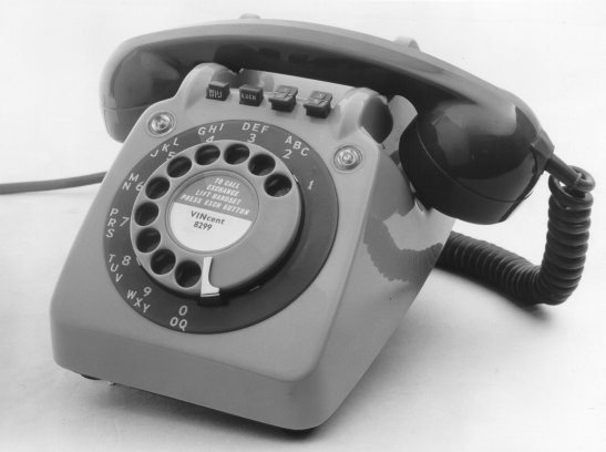
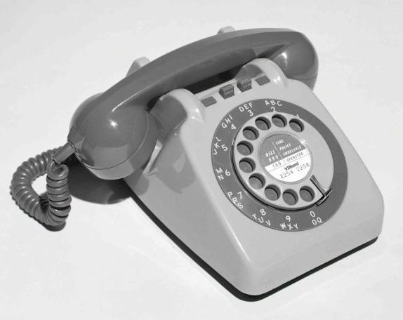
3 TELEPHONE, INTERCOM, No. 3/1
This telephone is used at a HES No. 3 installation which caters for one exchange line and up to five stations. The telephone is basically a Telephone No. 710 and has a cover (Part 6/DCO/627)which is provided with two lenses; it is fitted with a self-locking BELL OFF button in position A, an EXCH button in position B and two split buttons in each of positions C and D.

The moulded base (a standard item) is fitted with a special gravity switch and has been coded Part 4/DBA/107.
Fitted between the gravity-switch pillars in a sub-assembly known as a Switch, Composite No. 1A, which consists of a spring contact unit wired to a Strip, Connection, No. 155B, the assembly having seven flexible spade-ended leads for connection to the telephone circuit. The contact unit is held in position between the gravity-switch pillars by four screws and the connection strip is held at the rear of the pillars by two locating pins and a spring clip.
The plungers and spring contacts located in positions C and D of the latch- plate assembly form the intercom signalling circuits. The spring contacts and plunger in position B are contacts KX of the exchange line circuit, and these may be released either by replacing the handset or by pressing any one of the four buttons in positions C and D. The spring contacts in position A which are adjacent to position B, are contacts KH and these also operate when contacts KX are operated, but they can only be released by replacing the handset; these form the hold circuit of the exchange line. The remaining spring contacts in position A control the magneto bell cut-off or additional facilities. These springs are operated by a special plunger which is fixed to the latch plate by a bracket. The spring assembly is illustrated in
Diagram Q 422 and the button arrangement is shown in Diagram Q 424.
Fixed on the sides of the gravity-switch pillars are two Lamp-fittings, No. 16 (incomplete); viewed from the front of the telephone, the fitting on the left-hand side contains a Lamp No. 26H which provides the red lamp signals for the exchange line, whilst in the fitting on the right-hand side is a Lamp No. 26i which provides the engaged signal for the intercom circuit.
The d.c. buzzer for intercom calling is fitted onto the cord grommet frame and the complete assembly has been coded Buzzer No. 2B-2.
The telephone is fitted with a Cord, Inst, No. 20/03AJ, ..., 72in which is terminated with the multiple cables onto a Block, Terminal, No. 37.
The telephone is normally fitted with a Handset No. 3. The CB telephone has a Dial, Auto, Dummy, No. 6A, The complete circuit of the telephone is shown in
Diagram Q 422 and the wiring of the Switch, Composite, No. 1A only in
Diagram Q 423. The instrument cord and cable connections for the telephone are shown in
Diagram Q 424. The telephone is available in black, grey and ivory. .
4 TELEPHONE, INTERCOM, No. 4/1
This telephone is used at a HES No. 4 installation which caters for one or two exchange lines and up to ten stations (exceptionally eleven stations).
The telephone mechanism is mounted on a metal base and is enclosed by a moulded plastic cover (Part 1/DCO/683).
The telephone when issued is fitted with a Handset No. 3 and a Connector No. 1046A. The overall dimensions of the telephone are approximately 11.25in (285mm) x 6.75in (170mm) x 4.75in (120mm) high.
Above the front sloping face of the cover containing the dial aperture, is an almost horizontal face in which is a rectangular aperture for the press-buttons of the key unit. Over the rectangular aperture and surrounding the press-buttons is a separate escutcheon which is sprung into place and clips onto the metal face of the key unit. This escutcheon contains the station identification labels with their clear plastic covers and the lenses for the exchange line lamps. The labels and plastic covers are removed by pressing at the end of the plastic cover with the blunt end of a pencil or similar object; this causes the middle to bow upwards where the cover and label may be gripped and pulled gently upwards. If the label does not rise with the cover it may be eased up by inserting a pin at the middle by the side of the label and levering gently upwards. The escutcheon is removed by inserting a thin blunt edged blade, or finger tip under the chamfered edge at the back and springing off the rear clip, then lifting upwards to release the front spring clip. In front of the handset rest there is provision for four press-buttons which are used to control the bell cut-off facility and any additional facilities that may be provided.
The telephone cover is fixed by two screws in the handset rest and by a screw in the front of the dial mounting.
The press-buttons are in two rows, from left to right there are the two ivory exchange line buttons engraved 1 or 2, two smaller ivory exchange line release buttons engraved R; ten grey press-buttons for signalling and speaking
to other stations over the intercom circuits, and the single ivory conference button engraved C.
At the front of the base are two bell gongs, over which Relay-units Q 527 and Q 528 (see para 18 and 19) may be mounted as required. The magneto bell is a Bell No. 59A with long flexible leads and has been coded Bell No. 59A-2.
Behind the bell and across the base 'is a printed circuit board with the components of a standard 700-type telephone transmission circuit.
The key unit is in two parts; a metal frame carrying spring-sets for the exchange lines and intercom circuits, and a press-button assembly.
The metal frame screwed to the base of the telephone, carried on each side, the spring assembly of an exchange line and a printed board with spring contacts riveted to it, for intercom signalling and speaking.
At the end of the frame near the exchange line spring contacts is a plunger assembly which operates on second and subsequent overpresses of an exchange press-button. The plunger operates a spring-set to provide operator-recall facility to either exchange line circuits. A second spring assembly inside the frame operates when the station press-buttons are overpressed and provides the intercom signalling condition.
At the end of the frame near the conference button are a number of `polytags' carrying resistors associated with lamp circuits etc.
On the top, near each of the four corners of the frame, is a lug which carries a Lamp-fitting No. 19 and a Lamp No. 41E. The press-button mechanism is held in the frame by a countersunk screw at each corner of the top plate.
On the left-hand side of the base, beneath the dial mounting, is a metal bracket which carries a d.c. buzzer (Buzzer No. 2B-3) for intercom calling.
Behind the key unit frame is a 72-way double-sided terminal block. On the top side is the telephone wiring; both soldered and screwed terminations. The instrument cord, a Connector No. 1046A, and any straps that may be required are terminated on the underside and these terminals are exposed by removing a cover plate from the base.
Over the cord entries at the rear of the base is a metal bracket which carries the intercom transmission feed coil and its associated resistors and capacitor.
The telephone is connected to the multiple cabling via a Box, Connection No. 6A. The circuit and connector connections of the telephone are shown in
Diagram Q 540. The telephone is available in black, grey and ivory.
The weight of the complete instrument is 81 lb.
5 BLOCK, TERMINAL, No. 37...
The Block, Terminal No. 37... is used at HES No. 3 installations to terminate the multiple cables and Telephone, Intercom No.3/1 at multiple stations. It is also used with a Control-unit Q 535 (see par 21) at a HES No. 4 installation.
The Block Terminal, No. 37... consists of a moulded plastic base (Part 1/DBA/99) on which is mounted a terminal block (Part 1/DBL/91), containing 25 double-sided screw terminations the tablet and base being enclosed by a moulded plastic cover (Part 1/DCO/62.5). At one end of the cover is a cut-out for cord entry and at the other end are three knockouts for cable entry.
The base has been modified to include a hole for back entry of cable and fixing holes for mounting the Block, Terminal No. 37... over square type conduit outlet boxes, i.e. standard outlet boxes with 2.75in (70mm) fixing centres.
6 BOX, CONNECTION, No. 6A
The Box, Connection, No. 6A has a base area of approximately 6.25in (160mm) x 5.75in (145mm) and is nearly 2in (50mm) high.
Mounted on the metal base is a Connector No. 203B55B,, which is a 55-pin plug. Also fixed to the base on raised pillars are two 28-way terminal blocks (Part 1/DST/861). The inserts of the terminal blocks have screw terminals for multiple cabling on the front side, and solder terminals on the rear side which are wired to the pins of the Connector No. 203B55B. At the side of the connector is a bracket to retain the grommet of the telephone instrument cord (Connector No. 1046A). Also in the base is a hole for back entry of cables.
The grey moulded plastic cover is held on by two fixing screws, and the sides contain knockouts for cable entry and a cut-out for the cord entry. Details of the wiring between the connector and terminal tablets are given in
Diagram Q(L) 510. 7 BOX, CONNECTION, No. 7A
The Box, Connection, No. 7A is identical in size and shape to the Box, Connection No. 6A. The metal base of the Box, Connection No. 7A provides mounting on raised pillars for three 28-way double-sided terminal tablets (Part 1/DST/861). These tablets have screw terminals on front and rear sides. There is no provision in the base for back entry of cables. The sides of the moulded plastic cover contain knockouts for cable entry. Typical uses of the Box, Connection No. 7A are shown in
Diagram Q 508. 8 WALL-MOUNTED RELAY-UNITS
Two sizes of metal case have been introduced for use with HES No. 3 and No. 4.
Relay-unit Q 405 is contained in a Case No. 131... which has a mounting surface of 12ins (305mm) x 4.5ins (110mm). All other wall-mounted units are contained in Case No. 133... which has a mounting surface of 12in (305mm) x 8.75in (220m). Both cases extend 7.25in (185mm) from the mounting surface.
Circuit components are mounted on a metal plate which is hinged to the baseplate and the wiring form from the components is terminated on a connection strip, which is fixed to the baseplate. Cable entry is via a hole fitted with a grommet in the baseplate.
A clear space of 6ins (152mm) must be allowed on the left side of the units when fixing to the mounting surface. This space allows full movement of the hinged plate, with access to the wiring of the relays etc.
A description of each wall-mounted relay-unit is given in para's 9 to 14.
9 RELAY-UNIT Q 405
Relay-unit Q 405 is provided at HES No. 3 installations which have multiple stations only. The unit contains the circuits which control the lamp signals in the Telephone, Intercom, No. 3/1, and the transmission feed relay for the intercom circuit. The wiring of the unit and the multiple cable terminate on a connection strip (Part 1/SST/71) the cable being connected to the screw terminals.
Wiring details are shown in Diagram. Q 405 and in Diagram ID 174, which is pasted inside the cover.
Cable connections are shown in Diagrams Q 403 and Q 404.
When a HES No. 3 is working subsidiary to a switchboard with a low-power ringing source, it may be necessary to provide a local ringing supply, the output of which is controlled by relay contact RG2.
Diagram Q 417 shows details of alternative ringing arrangements when working a HES No. 3 subsidiary to a switchboard or when more than 'five bells are to be rung.
The complete unit weighs approximately 51lb. (2.5kg).
10 RELAY-UNIT Q 410
Relay-unit Q 410 replaces Relay-unit Q 405 at HES No. 3 installations when a non-multiple extension is required. In addition to the components and circuits of the Relay-unit Q 405, the Relay-unit Q 410 also contains the components and circuits which connect the two-wire line of a non-multiple extension to the multiple wiring of the system.
In this unit there is no spare contact on relay RG, and when a HES No. 3 with a non-multiple extension is worked subsidiary to a switchboard which has a low-power ringing source, it will be necessary to change relay RG. The relay should be changed for a Relay No. 9871, and the additional contact wired as shown in
Diagram Q 417, which gives details of alternative ringing arrangements. The relay RG must also be changed and wired to
Diagram Q 417, when more than five magneto bells are to be rung at any installation.
The unit wiring and the multiple cable are terminated on a connection strip (Part 1/SST/71), with the cable connected to the screw terminals.
Wiring details of the Relay-unit Q 410 are shown in
Diagram Q 410 and in Diagram LD 175, which is pasted inside the cover.
The complete unit weighs approximately 14lb. (6.3kg).
11 RELAY-UNIT Q 415
The Relay-unit Q 415 is provided when an inter-switchboard or private circuit is included in a HES No. 3 installation, and is fitted in addition to Relay-unit Q 405 or Q 410.
Relay-unit Q 415 contains a number of circuit elements, which may be strapped according to the type of signalling being used on the circuit.
The wiring details of Relay-unit Q 415 are shown in
Diagram. Q 415 and in Diagram LD 180, which is pasted inside the cover.
The connections required when using the Relay-unit Q 415 are shown in
Diagrams Q 441 to Q 447. Signalling limits for this unit are the same as for a Unit, Auxiliary Apparatus, No. 97 and are given in P1061.
The unit wiring and multiple cables together with the required strappings shown in
Diagram Q 441 are terminated on two Strips, Connection, No. 121D mounted back to back; these are all soldered connections.
The complete unit weighs approximately 15 lb. (6.8 kg).
12 RELAY-UNIT Q 516
The Relay-unit Q 516 is fitted to all HES No. 4 installations, and contains the components and circuits which control the lamp signals and exchange line ringing signals at a Telephone, Intercom, No. 4/1 fitted at a multiple station. Relay contacts within the unit are also available, when required, to extend signal and start conditions to the relay-unit of non-multiple extensions or private circuits.
Current through each of the series connected exchange line engaged lamp circuits of a Telephone, Intercom, No. 4/1 is controlled by a transistor circuit. The transistor is mounted on a heat sink which also carries the associated resistors, capacitor and rectifier; this complete assembly has been coded Regulator No. 4A.
The Regulator No. 4A is fixed by two screws to the hinged plate and joined to the circuit by three flexible spade-ended leads. Care must be taken to ensure that these leads are correctly connected otherwise the transistor may be seriously damaged. The regulator is adjusted during manufacture to pass 104mA (- or + 12 ma) under load conditions, and should any component become faulty, the complete regulator must be changed.
Mounted on the baseplate of the relay-unit is a clip to hold a Connector No. 203C55C, which is a 55-way connector that has been provided with a number of straps between certain sockets, and is intended for use at multiple stations where a Telephone, Intercom, No. 4/1 has been disconnected for repair or replacement. By replacing the telephone socket with a Connector No. 203C55C the series circuits of the installation are maintained and service is continued at all other stations. The connections provided in the Connector No. 203C55C are shown in
Diagram Q 510. Wiring details of the Relay-unit Q 516 are shown in
Diagram Q 516 and in Diagram LD 192, which is pasted in the cover.
The complete unit weighs approximately 12lb. (5.4kg).
13 RELAY-UNIT Q 519
The Relay-unit Q 519 is provided at a HES No. 4 installation to connect the two-wire line of a non-multiple extension to the multiple wiring.
Circuits in the unit provide the non-multiple extension with most of the facilities of a multiple station; these facilities are fully described in C3031.
A Strip, Connection, No. 121M provides the terminating point for the unit wiring, multiple cables and strappings as required. Straps that may be needed should be connected on the permanent wiring side of the Strip, Connection, No. 121M; and the multiple cables terminated on the opposite side.
Details of the wiring are shown in Diagram Q 519 and in
Diagram LD 195, which is pasted inside the cover. When a Relay-unit Q 519 is provided, a Control-unit Q 535 or Q 537 (see para's 21 and 22) is always fitted at the main station and the operation of the Relay-unit Q 519 should be studied in conjunction with the operation of the Control-unit Q 535 or Q 537. Circuit elements and explanatory, notes are shown in diagrams in the Q 5... series.
The complete unit weighs approximately 17lb. (7.7kg).
14 RELAY-UNIT Q 524
The Relay-unit Q 524 is provided at a HES No. 4 installation to connect the two wires of a private circuit to the multiple wiring.
The unit contains circuit elements which may be connected by strappings on the Strip, Connection, No. 121M, to terminate the circuit at the HES No. 4 according to the type of signalling to be used. The cable connections and straps required for various signalling groups are shown in
Diagrams Q 561 to Q 567. Wiring details of the unit are shown in
Diagram Q(L) 524 and in Diagram LD 194, which is pasted inside the cover.
Signalling limits for the Relay-unit Q 524 are the same as for a Unit, Auxiliary Apparatus, No. 97 and these are shown in P1061.
Straps should be connected on the permanent wiring side of the Strip, Connection, No. 121M and cabling should be terminated on the opposite side.
The complete unit weighs approximately 17lb. (7.7kg).
15 RELAY-UNITS MOUNTED IN TELEPHONES, INTERCOM
Certain facilities that are available to both HES No. 3 and No. 4 installations are provided by fitting small relay-unit into a Telephone, Intercom No. 3/1 or No. 4/1 and modifying the instrument cord connections.
These units consist of a Relay No. 16/... or Relay No. 23/6 mounted on a metal mounting plate which is secured over a bell gong.
Other components may also be included, terminated on `polytags' pressed into the metal mounting plate.
The various relay-units for fixing inside Telephones, Intercom, are described in para's 16 to 19.
16 RELAY-UNIT Q 408
The Relay-unit Q 408 is provided in a Telephone, Intercom No.3/1 when the instrument is to have restricted exchange service.
The unit consists of a Relay No. 16/1 and two diodes (Valves, Electronic, CV 7040) on a mounting plate (Part l/DMO/102), and has spade-ended flexible leads for connection to the telephone circuit.
Diagram Q 408 shows the wiring of the unit and the connections within the telephone.
17 RELAY-UNIT Q 409
The Relay-unit Q 409 is provided in a Telephone, Intercom No.3/1 when the instrument is to have monitoring facilities.
The unit consists of a Relay No. 1612 wired with spade-ended flexible leads on a mounting plate (Part 2/DMO/102).
Diagram Q 409 shows the wiring of the unit and the connections within the telephone. Relay-Units No. 408 and 409 are mounted over the right-hand side bell gong.
18 RELAY-UNIT Q 527
The Relay-unit Q 527 is fitted in a Telephone, Intercom No.4/1 when the station is to have restricted exchange service.
When exchanges service restriction applies to only one line the Relay-unit Q 527 should be used and connected to the appropriate line. When both lines are to be restricted the Relay-unit Q 527 should be connected to the line on position one of the telephone and a Relay-unit Q 528 (see par 19) connected to the line on position two.
The Relay-unit Q 527 consists of a Relay No. 16/1 and two rectifiers (Valves, Electronic, CV 8308) on a mounting plate (Part 3/DMO/102), and has flexible spade-ended leads for connection to the telephone. Details of the wiring and telephone connections are given in
Diagram Q 527. The Relay-unit is mounted over the left-hand side bell gong.
19 RELAY-UNIT Q 528
The Relay-unit Q 528 is fitted in a Telephone, Intercom No. 4/1 when both lines are to have restricted exchange service. The unit includes a mounting plate (Part 1/DMO/102) for mounting over the right-hand side bell-gong but in all other respects the Relay-unit Q 528 is identical to the Relay-unit Q 527. Details of the Relay-unit Q 528 are included in
Diagram. Q 527. 20 TWO-WIRE CIRCUIT CONTROL-UNITS AT MAIN STATIONS
When a non-multiple extension or private circuit is fitted at a HES No. 4 installation a control-unit must be fitted at the main station. This unit provides the circuit calling and clearing supervisory, and exchange line testing circuits. There are two sizes of control-unit, Control-unit Q 535 which caters for one circuit and is described in par 21, and Control-unit Q 537, which caters for up to four circuits and is described in par 22.
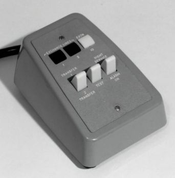
21 CONTROL-UNIT Q 535
The Control-unit Q 535 is a desk unit measuring approximately 3.5in (90mm) wide x 5.5in (140mm) front to back and 2.75in (70mm) high; it is fitted adjacent to the Telephone, Intercom, No. 4/1 at the main station.
The unit is contained in a Mounting D 92155 using a cover (Part 1/DCO/672, Grey), and a face plate (Part 1/DPL/2136). The 'EXCHANGE LINE' lenses are Caps, Lamp, No. 79C, Red and the 'EXTENSION' lens is a Cap, Lamp, No. 79C, White. The lamps used are Lamps No. 2-45V. The lamps and lenses are easily replaceable but other components are soldered in and should not normally be changed in subscribers' premises.
The cord associated with the unit is a Cord, Inst, No. 18/04AJ, Grey, 72ins (1.8m) and this is terminated with the cabling onto a Block, Terminal, No. 37..., both must be ordered separately.
Diagram Q 535 shows the wiring details of the unit and Q 1015 explains the facilities of the unit.
|
 |
|
Control Unit Q535 |
The unit is available in grey only.
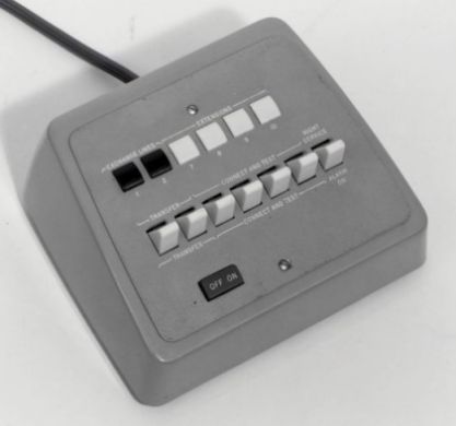
22 CONTROL-UNIT Q 537
The Control-unit Q 537 is a desk unit measuring approximately 6.75in (170mm) wide x 5.5in (140mm) front to back and 3in (75mm) high; it is fitted adjacent to the Telephone, Intercom, No. 4/1 at the main station.
The unit is contained in a Mounting D,92199 using a cover (Part 1/DCO/676, Grey) and a face plate (Part 2/DPL/2135). In addition to the parts contained in Control-unit Q 535 (see par 21) the Control-unit Q 537 contains four key circuits which are used to connect non-multiple extensions and private circuits for intercom calls. When used at an installation with 2nd choice main station facilities, the Part 2/DPL/2135 is changed (see C3036).
This unit is issued without a cord and Q 3015 describes the conditions governing which cord should be fitted.. When a Cord, Inst, No. 18/04AJ, Grey, 72ins (1.8m) is fitted, a Block, Terminal, No. 37... must be used to terminate the instrument cord and cable. When a Connector No. 1046A or No. 1052A is fitted, a Box, Connection, No. 6A must be used to terminate the connector and cable.
Diagram Q(L) 537 shows the wiring details of the unit and C3031 explains the facilities of the unit.
 |
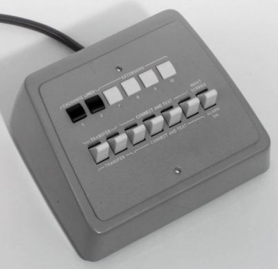 |
| Control Unit Q537 |
Control Unit Q537 Second
Choice |
23 NON-MULTIPLE EXTENSION TELEPHONE
A Telephone No. 710 is used to terminate the non-multiple extension. The components to be ordered separately and fitted in the telephone are fully described for the HES No. 3 in
Diagram Q 420, and for the HES No. 4 in Diagram Q 550.
Telephone No. 710 fitted with buttons appropriate for a
Non-Multiple Extension 24 EXTENSION BELLS ETC
Standard magneto bells, d.c. bells and buzzers are used when extension bells etc are required.
Diagram Q 419 shows the connections for HES No. 3 and Diagram Q 545 shows the connections for the HES No. 4.
25 ADDITIONAL RECEIVERS
A Receiver, Watch, No. 8T and a Hook, Receiver, AG are used.
26 LABELS
Particulars of dial labels for Telephones, Intercom No. 3/1 and No.4/1 are given in C3034 and C3036 respectively, and the labels are described in M0010.
When issued, Telephones, Intercom No. 4/... are fitted with station identification labels (Labels No. 469/1 and 2 and these are described together with Labels No. 469 in C3036.
27 INSTRUMENTS CORDS AND CONNECTORS
There are two instrument cords and two connectors available for use on HES No. 3 and No. 4 equipment.
Cord, Inst, No. 20/03AJ, 72ins (1.8m) is normally fitted to Telephones, Intercom, No. 3/1.
Cord, Inst, No. 25/04AJ, 72ins (1.8m) replaces Cord, Inst, No. 20/03AJ, 72 ins (1.8 m) when extra conductors are needed.
Both cords have at one end 4ins (115mm) spade-ended conductor tails for Connection to the telephone, and at the other end, have the spade-ended tails formed into two rows of ten. Each row is held in position by strips of flexible plastic, which are moulded over the shanks of the spade terminals. The remaining five conductors of the Cord, Inst, No. 25/04AJ, ..., 72 ins (1.8 m) are left free. The plastic 'harness' assists in quick and accurate connection of the conductors to the Block, Terminal, No. 37...
Each cord is stocked in three colours: black, grey and ivory, and in two lengths: 72 ins (1.8 m) and 120 ins (3.0 m).
The Connector No. 1046A is normally fitted to a Telephone, Intercom,, No. 4/... and may be fitted to a Control-unit Q 537 if required.
The Connector No. 1052A replaces Connector No. 1046A when. extra conductors are needed.
Both connectors have at one end, 4.2ins (115mm) spade-ended conductor tails for connection to the telephone or control-unit. At the other end, soldered to the conductors, is a Connector No. 203C55A, which is a 55-way socket for connection to the Box, Connections, No. 6A.
Both connectors are stocked in three colours, black, grey and ivory, and in two lengths, 72ins (1.8m) and 120ins (3.0m) Connectors, with 120ins (3.0m) cords are coded Connectors No. 1046B and No. 1052B.
28 CABLE
The cable used for HES No. 3 and No. 4 installation is Cable, Distribution ... (12W, 24w or 41w), /0.5mm. The size and type of cable to be used is given in C3034 for the HES No. 3 and C3036 for the HES No. 4.
29 POWER EQUIPMENT
The HES No. 3 and No. 4 are mains operated installations, and standby batteries are not provided. A Power-unit No. 51A is provided for the HES No. 3 and a Power-unit No. 52A for the HES No. 4.
30 RINGING SUPPLY
The Converter, Ringing, No. 7, which is mounted inside a Power-unit No. 51A or No. 52A is normally provided when a local ringing supply is required for a non-multiple extension or private circuit. Power-unit No. 100A/1 and 100A/2 for use with HES No. 3 and 4 respectively are equipped with Converters Ringing No. 7 and should be provided at installations initially requiring a ringing supply.
Formerly EI Telephones, Stations, Q1016
TELECOMMUNICATIONS INSTRUCTION
C MARKETING INSTALLATION
3 Internal
C3034
Issue 2, October 1973
HOUSE EXCHANGE SYSTEM
No. 3 Installation
1 SCOPE OF INSTRUCTION
This Instruction describes the installation of the House Exchange System
(HES) No. 3 to which has been given the sales name of 'Key-master'.
The facilities available in the BES No. 3 are described in C3030.
2 CONTENTS
| |
Paragraph |
| ADVICE NOTES |
3 |
| EQUIPMENT REQUIRED FOR CB MANUAL AND AUTOMATIC AREAS |
4 |
| EQUIPMENT REQUIRED FOR LB AREAS |
5 |
| POWER SUPPLY |
6 |
| EXCHANGE LINE LIMITS |
7 |
| LAYOUT OF THE SYSTEM |
8 |
| UNSUITABLE SITUATIONS |
9 |
| EXTERNAL MULTIPLE STATIONS |
10 |
| NON-MULTIPLE EXTENSION LINE |
11 |
| CABLING OF THE SYSTEM |
12 |
| NUMBERING OF STATIONS |
13 |
| BLOCK, TERMINAL, No. 37B |
14 |
| BLOCK, TERMINAL, No. 37B - FITTING |
15 |
| BLOCK, TERMINAL, No. 37B - WIRING |
16 |
| BLOCK, TERMINAL, No. 37B - SECURING THE CABLE |
17 |
| FITTING OF TELEPHONES, INTERCOM, NO. 3/1 |
18 |
| MAIN STATION |
19 |
| MULTIPLE STATIONS |
20 |
| NON-MULTIPLE EXTENSION |
21 |
| RELAY-UNITS |
22 |
| POWER-UNIT NO. 51A AND CONVERTER, RINGING, NO. 7 |
23 |
| MOUNTING OF RELAY-UNITS AND POWER-UNIT |
24 |
| EARTH CONNEXION |
25 |
| CORDS |
26 |
| DIAL CENTRE LABELS |
27 |
| EXTENSION BELLS AND BUZZERS |
28 |
| RESTRICTED AND BARRED EXCHANGE SERVICE |
29 & 30 |
| MONITORING |
31 |
| SUBSCRIBER PRIVATE METERS ETC |
32 |
| ASSOCIATION WITH PBX |
33 |
| CONNECTING CIRCUITS BETWEEN TWO HOUSE EXCHANGE SYSTEMS |
34 |
| HEARING AIDS |
35 |
| TESTING |
36 |
| MULTIPLE WIRING CONTINUITY TESTS |
37 |
| INSULATION TESTS OF EXCHANGE LINE MULTIPLE |
38 |
| TESTS AT MULTIPLE STATIONS |
39 |
| TESTING THE NON-MULTIPLE EXTENSION |
40 |
| TESTING A PRIVATE CIRCUIT |
41 |
3 ADVICE NOTES
The Advice Note for a HES No. 3 Keymaster will specify the type of exchange
line connexion and the number of multiple stations to be Provided. The
Advice Note will also specify whether a nonmultiple extension is required
and such miscellaneous requirements as extension bells and exchange line
barring and/or monitoring.
4 EQUIPMENT REQUIRED FOR CB MANUAL AND AUTOMATIC AREAS
Table 1 shows the main items or equipment required for an installation.
TABLE 1
| Item |
Use |
Quantity |
Remarks |
| Telephone, Intercom No. 3/1 (F or
CE), Colour |
Multiple station telephone |
One per multiple station |
No. 3/1F for use in automatic areas
No. 3/1CB for use in CB manual arena Diagram Q422.
|
| Telephone No. 710 (F or CB), Colour
|
Non-multiple extension telephone |
|
For additional items required see
Diagram Q420.
|
| Block, Terminal No. 37B |
At multiple stations, to terminate
cable and Telephone Intercom, No. 3/1 (F or CB)
|
One per multiple station |
|
| Relay-unit Q405 (Note 1) |
Common equipment |
One per installation |
Used at installations with
.multiple stations only. Diagram Q405.
|
| Relay-unit Q410 |
Combined common equipment and
non-multiple extension., speech and signalling equipment
|
One per installation |
Used only at installations fitted
with a non-multiple extension. Diagram Q410. |
| Power-unit No. 51A or 100A/1 |
Power supply for signalling, local
speech etc |
One per installation |
Supplies 1 amp maximum at 50V d.c.
Diagrams N636, Q403, Q404, Q435.
|
| Converter, Ringing, No. 7 |
To call non-multiple extension |
One per installation if required |
Only required when non-multiple
extension is fitted. Converter is fitted inside Power-unit
No. 51A. Diagrams N654, Q403, Q404 and Q435.
|
| Relay-unit Q415 |
Terminates circuit from remote
switchboard or HES |
One per circuit |
Fitted in lieu of a multiple
station. Adaptable for various signalling groups. Diagram Q415.
|
| Relay-unit Q408 |
To bar exchange service |
One per station to be barred |
Fitted inside telephone at each
station to be optionally barred. Diagram Q408.
|
| Relay-Unit Q409 |
Monitoring unit |
|
Fitted inside telephone which is to
monitor exchange line. Diagram Q409.
|
NOTE:- Should an installation of multiple stations later
require a non-multiple extension, the Relay-unit Q405 must be recovered and
a Relay-Unit 0410 fitted.
5 EQUIPMENT REQUIRED FOR LB AREAS
The equipment shown in Table 1 should be used but in addition an auxiliary
apparatus unit must be associated with the exchange line to present CE
conditions to the House Exchange System.
In CBS No. 2 exchange areas, a Unit, Auxiliary Apparatus
CBS 536 (Diagram CBS 536) is required for the exchange line. The unit will
normally be fitted at the public exchange. In magneto exchange areas a Unit,
Auxiliary Apparatus, CBS 107 (Diagram, CBS 1074) is required for the
exchange line; the unit will be fitted at the public exchange.
6 POWER SUPPLY
The power supply is derived from a Power-unit No. 51A which is mains
operated; Q0020 refers. A suitable mains connexion point is needed close to
the position chosen for mounting the power-unit and relay-unit (see par 22).
The mains outlet must be a 3-pin BS socket (preferably with switch) with the
third pin effectively earthed. If a suitable mains outlet does not exist the
subscriber should be asked to provide one. A copy of form A188 should be
given to the subscriber at each installation. The power-unit must be fitted
near to the relay-unit (see par 24) and multiple cabling must be kept to the
minimum to prevent excessive voltage drop. A long flexible mains lead should
not be fitted to connect to a distant mains point.
7 EXCHANGE LINE LIMITS
The telephone instruments used in the HES No. 3 contain the standard
700-type transmission circuit. Direct exchange line limits as stated in
A0102 are therefore applicable. When the installation includes a
non-multiple extension the signalling limit is reduced by 80 ohms and the
transmission limit by 1 dB to allow for the signalling relays in the
exchange line; these reduced limits include the 2-wire line to the
non-multiple extension (see C3010).
8 LAYOUT OF THE SYSTEM
Diagram Q 402 shows the layout of typical systems. The maximum length of
cable between the most distant multiple station and the power-unit should
not normally exceed 91 in. This ensures satisfactory operation of the
signalling circuits. In many installations the multiple will contain spare
conductors which may be bunched with the battery and earth wires to extend
the multiple of 137in.
9 UNSUITABLE SITUATIONS
Very damp or dusty situations are unsuitable for House Exchange Systems. If
damp conditions are found locally during the installation of a system, the
sites of the Block, Terminal, No. 37B and the power- and relay-units must be
chosen to avoid, them. The cables should preferably enter the terminal block
from below; this will prevent moisture which may condense on cable sheaths
from running into the block.
10 EXTERNAL MULTIPLE STATIONS An external multiple
station may be provided, exceptionally, if satisfactory cabling arrangements
can be made. The transmission and signalling limits are the same as those
applicable between internal multiple stations.
11 NON-MULTIPLE EXTENSION LINE
The running of the 2-wire extension line to the non-multiple extension
(whether internal or external) and the fitting of the non-multiple extension
telephone should follow ordinary subscribers' installation practice. Diagram
Q 420 shows the non-multiple extension telephone. It should be noted that a
signalling earth connexion is required at this extension.
12 CABLING OF THE SYSTEM
The cabling for internal multiple stations should be in accordance with
standard practice using Cable, Distribution 3597B 24W/0.5mm. For external
multiple stations the seine cable will often be suitable but where heavier
conductors or sheathing are necessary, an external type of cable may be
used.
13 NUMBERING OF STATIONS
Stations should normally be numbered in sequence according to their position
in the multiple cabling (see Diagram Q402). If a non-multiple ext' ion is
provided it is always connected at the end, of the multiple and becomes the
last station.
14 BLOCK, TERMINAL, No. 37B
Block, Terminal, No. 37B consists of a terminal strip screwed to a moulded
base which has a moulded clip-on cover. 'Knock-outs' are provided in the
base and cover for cable entry.
There are 25 terminal insets in the strip in two rows of
ten terminals and a centre row of five terminals. Terminal screws are fitted
on both upper and lower faces of the strip.
15 FITTING
The positions of flocks, Terminal, No. 37B will be decided by the position
of their associated intercom telephones, and the two should be considered
together so that they will be within the range of the standard 72 in cords
fitted to the telephones. Normally, terminal blocks are mounted directly on
to walls or other permanent mounting surfaces, but never directly on floors.
Where floor fixing is unavoidable, the block should be mounted on a Tablet,
Polished Hardwood, No. 2 and care should be taken in siting the terminal
block to minimize the dangers due to water, cleaners' equipment, movable
furniture etc. Exceptionally, blocks may also be mounted on a Tablet,
Polished Hardwood, No. 2 if it is considered that heavy condensation is
likely to occur inside the terminal block when they are mounted normally or
if the block is fitted in association with wall outlets of under-floor duct
systems.
16 WIRING
Diagrams Q403 and Q404 show the terminal block wiring for typical
installations. The cable-ends should be stripped and terminated in the
standard manner to the screws on the underside, of the terminal strip. Spare
conductors should be tied back and not cut off. It may assist the installer
if the terminal strip is reversed and secured to its base during the
connexion of the multiple cables, but care must be taken to ensure that the
cables are neither strained nor misplaced after the terminal strip has been
turned over to its correct position.
NOTE:- There are five signalling wires in the cable,
corresponding to the five stations; the line cord of the Telephone,
Intercom, No. 3/1 has four signalling conductors and one buzzer conductor,
each terminating on a particular terminal in the Block, Terminal, No. 37B.
The cable terminal connexions will therefore differ on each block. The
'home' buzzer is always connected to terminal 11 of the terminal block
serving the 'home' station, e.g. the wire on which station 2 is called
appears on terminal 13 at stations 1, 3, 14 and 5 and on terminal 11 at
station 2.
Attention is drawn to the straps to be fitted at the
first or last Stations. When the position of the cables in the terminal
blocks has been decided, the 'knockout' covering the appropriate cable
entries in the cover should be carefully broken out using Pliers, Cutting, 5in Square Nose and the rough edges filed off with a File, Half-round, Smooth
6 in. Only the entries to be used should be opened.
17 SECURING THE CABLE
As cable clamps are not provided in Block, Terminal, No. 37B the multiple
cables must be secured by cleating to the mounting surface at the point of
entry to the Block, Terminal, No. 37B.
18 FITTING OF TELEPHONES, INTERCOM, No. 3/1
Telephones, Intercom No. 3/1 are issued with a Cord, Instrument, No.
20/03AJ, ..., 72in fitted. The cord tails are fitted with spade terminals
and at the terminal block end are arranged in two rows of ten. Each row of
tags is spaced out to match the Block, Terminal, No. 37B terminal spacing
and moulded into a strip of soft plastic.
To connect the instrument cord to the terminal block all
the outer 20 terminal screws are withdrawn two complete turns. The spade
terminals in their plastic strip are then pushed under the cupped washers so
that the numbering on the plastic strip corresponds to that of the terminals
in the block, and the screws are then tightened. Before replacing the cover,
secure the cord grommet in the slot provided in the base. A Block,
Terminal No. 37B with cord and harness fitted is shown in Diagram Q421.
19 MAIN STATION
One multiple station in each installation will be designated the 'main
station'. At this station the strap between T16 and T17 in the telephone is
removed to make the bell cut-off key ineffective and so ensure that the bell
always rings on incoming exchange calls. The main station may also be
required to control additional facilities including night service at the
non-multiple extension; in these circumstances the BELL-OFF button must be
changed for an appropriate Part .../DBU/341 colour (see Diagram Q430).
20 MULTIPLE STATIONS
If in addition the bell at any other multiple station is required to signal
all incoming exchange calls, the strap T16 and T17 must be removed. (see par
19). If the installation is connected to an exchange with a non-standard
ringing supply (e.g. a vibrator), it may not be possible to ring more than
two bells; bells at the remaining multiple stations should be permanently
short-circuited. by strapping terminals T16 and T4.
Telephones, Intercom No. 3/1 are issued with
station-calling buttons numbered 1-4. At installations with five stations
the number plates on certain buttons must be reversed, to show the figure 5
which is provided at the back, in accordance with Diagram Q424.
If the intercom, telephone is removed from a working
multiple station, series circuits must be maintained by strapping the
terminals 1-6,2-5, and 17-18 in the station terminal block.
21 NON-MULTIPLE EXTENSION
The Telephone No. 710 at the non-multiple extension must be fitted with two
Switches No. 5A-4, a Thermistor No. 1A-1, Press-buttons 22/DBU/260,
23/DBU/260/Colour, and Plungers 1/DPL/378, 1/DPL/379. The press-button
engraved EXCH is fitted in position B and that engraved. EXTN in position C.
A Switch No. 5A-4A and Part No. 1/DPL/379 are fitted in position. B with the
extension piece of the plunger facing position C. A Switch No. 5A-4 and Part
No. 1/DPL/378 are fitted in position C; the pin of this plunger must engage
with the slot in the other plunger. The latches must be arranged to lock
plunger C but not plunger B; release of C is by the gravity switch.
(NOTE: A switch 5A-4 with metal bracket or switch 5A-4A
must be fitted in position B. A switch 5A-4, all plastic construction, may
be fitted in position C.).
Other stores items required and the connections at the
non-multiple extension are shown in Diagram Q420.
22 RELAY-UNITS
Signalling and switching relays and the transmission bridge
for the intercom circuit are contained in wall-mounting units. Relay-unit
Q405 is required at installations with multiple stations only. Relay-unit
Q1410 replaces Relay-unit Q405 at installations with a non-multiple
extension. Relay-unit Q405 may be connected to either end of the multiple
but Relay-unit Q410 must be connected after the last multiple station (see
Diagrams Q402, 403 and 404).
When a HES No. 3 system is to be connected by a private
circuit to another subscriber's installation an additional unit, Relay-unit
Q415, will be required for each private circuit, see Diagrams Q415 and Q441
to Q447.
23 POWER-UNIT No. 51A AND CONVERTER, RINGING, NO. 7
Diagrams N636, N654, Q403, Q404 and Q435 refer. The maximum d.c.
supply required for a fully equipped HES No. 3 is approximately 750mA at
47.6-50V. The d.c. supply is obtained from a mains-operated Power-unit No.
51A requiring a mains input of 200-250V 50Hz; the loading due to the power
unit is 140-90 watts. Power-unit No. 51A is described in Q0020.
When a HES No. 3 installation includes a non-multiple
extension a 25 Hz ringing supply is required. This is obtained from a
Converter, Ringing No. 7 which is fixed to the base-plate of Power-unit No.
51A (see Q0006). A Converter, Ringing No. 7 will also be required in
conjunction with Relay-unit Q415 when generator signalling is used over a
private circuit. For new installations Power-unit No. 100A/1, which is
equipped with a Converter, Ringing No. 7, should be used.
24 MOUNTING OF RELAY-UNITS AND POWER-UNIT
To reduce cabling the relay-unit and power unit should be mounted close to
the end of the multiple on a suitable permanent surface. When deciding the
mounting position consideration must be given to access for maintenance
purposes. To ensure adequate ventilation of the Power-unit a minimum
clearance of 12in must be left between the lower edge and any horizontal
surface beneath it. The relay-unit should be mounted wherever possible
immediately above the power-unit, with space at the sides to allow full
opening of the hinged panel in the relay-unit.
The units are each provided with a grommeted hole in the
back plate for cable entry, and each unit has a terminal block fixed to the
back plate for cable termination.
25 EARTH CONNEXION
An efficient earth connexion must be provided for the power plant and
connected to the positive terminal of the 50V supply. The earth connexion
should not be obtained from the mains supply earth lead or conduit but it
may be taken from a main water pipe providing this is completely run in
metal pipework.
26 CORDS
Telephones, Intercom No. 3/1 are issued fitted with Cords, Instrument, No,
20/03M, ..., 72in. The positions of stations should, wherever possible, be
chosen to allow the use of the 72 in cord.. Exceptionally, cords 120 in or
180 in long, which are available on requisition, may be provided in lieu of
the standard length.
27 DIAL CENTRE LABELS At multiple stations in automatic
areas, Labels
Nos. 386A or 386B will normally be used. At the non-multiple extension in
manual or automatic areas and at multiple stations in manual areas, Label
No. 386E will normally be used (see M00l0).
28 EXTENSION BELLS AND BUZZERS
Separate or additional magneto bells may be connected to the exchange line
ringing circuit or multiple stations, but the total number of bells which
are to be rung must not exceed five. This may mean that one or more of the
bells in Telephones, Intercom No. 3/1 will have to be permanently
short-circuited (see paragraph 20).
One extension magneto bell may be provided at the
non-multiple extension in addition to the magneto bells, provided at
multiple stations.
Loud sounding bells may be provided as extension bells.
One d.c. bell or buzzer may be provided at each multiple
station as an extension of the buzzer signalling circuit.
Diagram Q419 shows how extension bells and buzzers are
connected and M0060 describes the bells and buzzers which may be used.
29 EXCHANGE SERVICE RESTRICTED
-
When a station is to be barred exchange line service,
except at the discretion of the main or other controlling station, a
Relay-unit Q408 should be fitted in the Telephone Intercom No. 3/1 at
the station to be restricted. To install the unit remove the right hand
bell gong fixing screw, place the unit over the bell gong with the relay
facing to the rear of the telephone and replace the screw through fixing
hole in the unit.
-
At the controlling station replace the "bell on-off"
button (Part 2/DBU/241) with a "Bar" button (Part 4/DBU/341, Colour) see
Diagram Q430. The pin securing the original button should be re-used.
Diagrams Q408 and Q422 show the connections for this facility.
30 EXCHANGE PROHIBITION
At stations to be prohibited exchange service the
exchange line together with the lamp and bell circuits must be isolated from
the telephone. These stations should be modified at the respective BT31 as
shown on Diagram Q401.
31 MONITORING The facility of monitoring exchange calls
is allowed at only one station of an installation. At the monitoring
station:-
-
Replace the "bell on-off" button (Part 2/1)BU1241)
with a button (Part 5/DBU/341, Colour) see Diagram Q430.
-
Remove the right hand bell gong fixing screw, place
Relay-unit Q409 over the bell gong with the relay facing to the rear of
the telephone and replace the screw through fixing bole in the unit.
-
Replace Cord. Instrument 20/03AJ.... by Cord
Instrument 25/04AJ... Colour, Connect Cord and Relay-unit Q409 as shown
in Diagram Q409.
-
The exchange line should be intercepted before
entering the multiple at station one, or another suitable point and
extended using spare multiple conductors or an additional cable, Cable
Distribution 3595B 4w/0.5mm, to the monitoring station. Connexions are
shown on Diagram Q409.
32 SUBSCRIBERS PRIVATE METER
A Meter No. 19 may be associated with the HES No. 3 by connexion to the
exchange line, before it enters the multiple or at a non-multiple extension.
The connexions for this facility are shown on Diagram Q412.
33 ASSOCIATION WITH A PBX
A HES No. 3 installation may be associated with a PBX by one of the
following methods:-
-
By terminating an extension from the PBX in place of
the exchange line, on a normal house exchange installation; standard
practice for the particular type of PBX concerned, should be followed to
determine the transmission and signalling limits for the complete
installation, and whether or not auxiliary units will be needed in the
connecting circuit. The house exchange station most distant from the
point of the PBX connexion, should be considered as a PBX extension, for
the purpose of determining the appropriate limits. If the HES No. 3 is
to have a non-multiple extension the normal signalling and transmission
limits are reduced by 80 ohms and 1 dB respectively.
-
Subject to satisfactory transmission, the HES No. 3
non-multiple station may be terminated as an exchange line, or private
circuit on the distant PBX switchboard.. Exchange calls cannot be
extended in either direction.
-
A Relay-Unit Q415 fitted in place of a multiple
station, and connected via a private or inter-switchboard circuit, will
usually provide all normal inter-switchboard facilities between a HES
No. 3 and a PBX. See Diagram Q441 to Q447 for connection for various
signalling systems.
-
An individual PBX extension or exchange line, may be
provided at each or any multiple station. See Diagram Q411 for
connexions.
-
Diagram Q 413 shows the connexions for providing
operator recall facilities on Telephone Intercom No. 3/1...
34 CONNECTING CIRCUITS BETWEEN TWO HOUSE EXCHANGE SYSTEMS
-
Two HES No. 3 systems may be connected together by a
private circuit using Relay-Units Q415 in place of a multiple station at
each installation. One installation should be wired in accordance with
Diagram Q444 the other to Diagram Q416. Exchange calls can be extended
from the installation wired to Dgm Q444.
-
An HES No. 3 system may be connected by a private
circuit to an HES No. 4 system. Relay Unit Q415 wired to Diagram Q446
replaces a multiple station at the HES No. 3 installation. Relay-Unit
Q524 connected as shown on Diagram Q567 replaces a multiple station at
the HES No. 14 installation. Exchange calls can be extended from the HES
No. 14 system.
-
An HES No. 3 installation may be connected, using
Relay-Unit Q410, to an exchange line position of HES No. 1, 2 or 14.
Exchange calls cannot be extended in either direction.
-
An HES No. 3 installation may be connected, using
Relay-Unit Q415, to a non-multiple position of an HES No. 1 or 2. This
requires modification to the Unit-Transfer No. 1� or 3, and allows
exchange calls to be extended to the HES No. 3.
-
The non-multiple extension of HES No. 1 or 2 may be
connected as on the exchange line of the HES No. 3. Subject to
satisfactory transmission and signalling, exchange calls can be extended
to the HES No. 3.
35 HEARING AIDS
Handset No. 11 may be provided, when required, at multiple and non-multiple
stations. See Diagram Q570 for connexions.
36 TESTING
Each new installation should be checked for:-
-
Continuity- of multiple wiring
-
Insulation
-
Function of circuits.
37 MULTIPLE WIRING CONTINUITY TESTS
After completion of multiple wiring, but before connecting the power-unit,
instruments or relay-unit, the continuity of the multiple between the first
and the last multiple stations should be tested. At the last terminal block
all terminals should be connected together temporarily.
At other terminal blocks (except the first)
series-connected circuits must be completed by temporary connexions at each
block: strap terminals 2 to 5, 1 to 6 and 17 to 18. From the first terminal,
block loop continuity tests should be made on each conductor in the
multiple, using a dry cell and a Detector No. 1. Diagram Q403 shows
how the multiple is connected at each terminal block.
38 INSULATION TEST OF EXCHANGE LINE MULTIPLE
After removing temporary connexions made for the continuity tests, but
before connecting the d.c. power supply, connect the relay-unit telephones
and exchange line. Arrange for exchange line to be insulation tested by test
clerk if appropriate. Tests made under this condition will automatically
include the non-multiple extension line and instrument, if fitted.
39 TESTS AT MULTIPLE STATIONS
Tests for the correct operation of the installation should be made as
follows:-
-
Make an outgoing call to the exchange from each
station. Check that the intercom engaged lamp glows on lifting the
receiver and that when the EXCH button is pressed the exchange engaged
lamp glows, as the intercom engaged lamp darkens.
-
Obtain an incoming exchange call, check at each
multiple station that the magneto bell rings, and that, except at the
main station, the BELL OFF button when operated short-circuits the bell.
Also check that the exchange line engaged lamp flashes in rhythm with
the exchange ringing.
-
Make an outgoing call to the exchange from station
No. 1, then hold and transfer the call to station No. 2. Repeat the hold
and transfer test at each of the remaining multiple stations. Check at
each multiple station that the exchange engaged lamp flashes while the
call is being held.
-
At each multiple station signal and speak over the
intercom circuit to the other stations in turn, then together as a
conference call. Check that the intercom engaged lamp glows at each
multiple station when the circuit is in use.
40 TESTING THE NON-MULTIPLE EXTENSION
When a non-multiple extension is fitted the following tests should be made
in addition to those in par 39:-
-
Call the main station. Confirm that the intercom
circuit engaged lamp glows when the non-multiple extension calls and
continues to glow during conversation.
-
Obtain a call from, and speak to, each multiple
station in turn.
-
Make an exchange cal1 and then transfer it to the
main station. Arrange for the main station to transfer the call back
after the non-multiple extension has cleared.
-
Operate the NIGHT SERVICE button at the main station,
then obtain an incoming exchange call and check that the bell rings at
the non-multiple extension.
-
The 50v d.c. supply should be disconnected by
switching off the mains input. Relay EX in Relay-unit Q410 will release.
Obtain an incoming exchange call and check that the non-multiple
extension bell rings and that the call can be answered.
41 TESTING A PRIVATE CIRCUIT
At the main station:-
-
Call the distant end and confirm correct operation of
audible and visual signals. Conduct speech test. Check that the
connection clears down correctly at both ends.
-
Obtain a call from distant end and check audible and
visual signals. Pass the call forward to each multiple station and check
engaged and clear down signals.
-
At installation where extension of exchange calls is
permitted make outgoing exchange call and extend this over private
circuit. Check for correct audible and visual signals. Check that the
call can be cleared from the distant end. Check incoming exchange
call.
Formerly El Telephones, Stations, Q3011.
THE POST OFFICE ELECTRICAL ENGINEERS
JOURNAL
Vol. 56, Part 1 (1963)
A Simplified House Exchange System
House Exchange
System No. 3
By
F. L. RANDALL and S. A. L. WARD
House exchange systems provide subscribers with a service that
is proving increasingly popular, hut the two systems at present
in use cannot meet modern transmission requirements and are
expensive to install. Some of the novel features of a new type
of installation that will replace the smaller of the existing
systems are described.
INTRODUCTION
HOUSE exchange system provides intercommunication facilities between a limited number of
stations as well as direct exchange-line service at
each of these stations, without the assistance of a central
switching position. Ideally, a house exchange system
combines the facilities provided by a house telephone
system or an extension plan with those of a small P.B.X.
by enabling users to select for themselves, by a simple
operation, the required facility.
The telephone instruments for an installation of the
above type must thus contain function-selecting and
signalling arrangements that are easy to manipulate but
which cannot be mis-operated to the detriment of the
service at other stations of the system. The mechanical
problems created by this requirement were first solved
satisfactorily in the house exchange systems introduced
by the Post Office in 1935. These two systems. House
Exchange Systems (H.E.S.) No. 1 and 2, cater, respectively, for one exchange line and up to six extensions
and two exchange lines and up to 11 extensions and
have proved increasingly popular with subscribers.
Several disadvantages have, however, become apparent in the techniques used in H.E.S. No. 1 and 2.
These
disadvantages include the following:-
-
The transmission circuit is not adequate for
exchange lines having the limits assumed for modern
cable-planning schemes.
-
The internal multiple cabling arrangements,
relying on a multiplicity of junction boxes, are costly in
materials and installation time.
-
Failure of the power supply prevents access to the
exchange line except from a non-multiple extension.
-
Considerable desk space is occupied by the telephone instrument and the auxiliary switching units.
These disadvantages have been overcome, existing
house exchange system facilities have been retained and
additional ones added in a new system, H.E.S. No. 3,
catering for one exchange line and five stations. The
new system is based on a 700-type intercommunication
telephone derived from the Telephone No. 710 and
coded Telephone, Intercom, No. 3/1, which is available
in three colours and in versions suitable for manual or
automatic exchange areas. Many of the principles
used in the H.E.S. No. 3 are also to be incorporated in
a larger system for two exchange lines and 10 stations
(H.E.S. No. 4) now under development as a replacement
for H.E.S. No. 2.
FACILITIES
In order to appreciate the facilities offered by the new
system it is necessary to distinguish between the various
types of station that can be associated with an H.E.S. No. 3 installation.
Multiple Station.
A multiple station is one equipped
with an intercommunication telephone and linked to
other multiple stations by a 21-wire cable.
Main Station.
The main station is a multiple station
that:-
-
always receives a ringing signal from incoming
exchange calls,
-
assists other stations not directly connected to
the multiple to originate local calls, and
-
controls certain additional facilities that are
described later.
Non-Multiple Extension. A non-multiple extension
is fitted if a station is located beyond the practicable
limit of the multiple cabling, e.g. in another building
Such a station is equipped with a Telephone No. 710
and is linked to the main installation by a 2-wire line.
As already mentioned, the new system can provide for one exchange line and up to five stations. A non-multiple extension may replace the last multiple station,
and private circuits to a P.B.X. or another house
exchange system can replace other multiple stations.
The following are the principal facilities afforded by
H.E.S. No. 3:-
Exchange Service.
Exchange calls are secret, and
outgoing service is available from any station which is
not specifically barred, including the non-multiple
extension. Access to the exchange line is obtained by
operation of a locking press-button with receiver-rest
restoration. Calls, incoming or outgoing, may be held
or transferred at any station, including the non-multiple
extension. Incoming exchange calls normally ring a
standard magneto bell included in the intercommunication telephone at each multiple station, and calls can
be answered by any station. The bell at most multiple
stations can be silenced by a locking bell off key, but
at the main station this key is permanently disconnected
from the bell circuit and may be used to control other
facilities.
Normal exchange service continues to be available at
all stations if the installation power supply fails.
Individual Exchange Lines.
A multiple station can
be connected to an individual exchange line or P.B.X.
extension not available to other stations; these stations
can share a common line or extension.
Local Intercommunication Calls.
A multiple station
can call any other station by means of a non-locking
press-button; buzzer signals are given at multiple
stations and magneto-bell signal at the non-multiple
extension. The non-multiple extension can only call
the main station, which assists by signalling the required
station. Local calls are not secret.
Conference Calls.
All stations can take part in a local
conference call; this facility is not available on exchange
calls.
Lamp Signals.
The exchange-line signalling circuit
includes a supervisory lamp, coloured red, which:-
-
flashes in time with exchange-ringing cadences,
-
glows steadily when the exchange line is answered,
-
flashes approximately twice a second when the
exchange line is being held by any station, and
-
glows steadily when a station takes over or is
ready to accept a transferred call.
A clear supervisory lamp glows when the local speech
circuit has been seized by any station.
Station-Engaged Signal.
A multiple station that
attempts to call an engaged station operates its own
buzzer.
Night Service.
The non-multiple extension can be
given incoming exchange service by means of switching
provided by the main-station instruments. Two-way
exchange service continues to be available at all multiple
stations.
Extension Bells and Buzzers.
Standard magneto
extension bells can be fitted at all stations, provided that
the total number of bells does not exceed five; one
extension bell may also be fitted at the non-multiple
extension. An additional buzzer can be connected to
each multiple station for local-call signalling. Association With Other Installations.
An H.E.S.
No. 3 can be connected to another house exchange
system or a P.B.X. either as a subsidiary installation or
by a private circuit. In some arrangements, night service
can be given over the private circuit.
Operator Recall.
When connected as a subsidiary to
a P.B.X., operator-recall signals can be given from any
multiple station, and the non-multiple extension can
recall the H.E.S. No. 3 main station, which can relay
the recall signal.
Exchange-Call Barring.
As an optional facility, any
multiple station can be denied exchange service except
at the discretion of the main station. Also, any station
can be permanently barred from exchange service.
Exchange-Line Monitoring.
One multiple station
can, if required, monitor exchange calls from other
stations while exchange calls from the monitoring station
remain secret.
Subscriber Trunk Dialling Facilities.
One subscriber's
private meter can be fitted to the installation. Permanent or optional trunk barring can be fitted at any
station.
FEATURES OF THE H.E.S. No. 3
With the object of achieving economies in equipment
and installation costs several departures from techniques
used in earlier systems have been introduced into the
H.E.S. No. 3.
Series-Multiple Exchange Circuit
To avoid the need for a line-connecting relay in each
telephone, without sacrificing the secrecy feature, a
series-connected exchange-line multiple has been adopted. With this arrangement the exchange line is normally
fed into and out of each station in turn, beginning with
station 1; priority of access can, however, be given to
any selected station by introducing the exchange line
into the multiple at the required point and returning it
to the normal sequence by means of spare conductors in
the multiple cable.
Single Intercommunication Speech Circuit
Only one speech circuit for local intercommunication
is provided in the multiple. Power for the telephone transmitters is fed to this circuit through a double-coil
high-impedance relay, the instruments being connected
in parallel across the circuit during local conversations.
This arrangement also provides a simple conference
circuit. The non-multiple extension has its own power
feed, but uses the common circuit for local calls.
Signalling for local calls is over a multiple conductor
exclusive to each station. The use of a common speech
circuit working on central-battery principles avoids the
need for a power-feeding transmission bridge in each
telephone.
Smaller Multiple
The H.E.S. No. 3 requires a minimum multiple of 17
conductors, a reduction compared with the earlier
system. As a standard 21-wire cable will normally be
used for the multiple, spare conductors will be available
for additional facilities, e.g. exchange-line monitoring or
for bunching with the power feeds to reduce voltage-drop at stations supplied by long cable runs.
Dual-Purpose Terminal Block
A new type of terminal box (coded Block, Terminal, No. 37A) is used both as a
multiple-cable junction box and as a connexion point for a multiple station. The
new terminal block contains a double-sided terminal
strip with two rows of 10 connexions and five additional
terminals between the rows; the terminal strip is housed
in a case moulded in toughened polystyrene and having
rectangular knock-out sections for cable entries and for
securing the standard cord grommet. The case has a
snap-on lid.
Multiple cabling is connected to the under-side of the
terminal strip; the upper-side accommodates the spade
tags of the instrument cord.
Each intercommunication telephone is equipped with
a 20-way cord 72 in. long. The spade tags at one end
of the cord are moulded into two flexible plastic strips
with 10 tags in each; the spacing and numbering of the
tags correspond with those on the terminal strip in the
block. The instrument is connected to the multiple
wiring by loosening the terminal screws to give sufficient
clearance for the spade tags to be pushed under the
cupped washers on the terminals, the screws then being
re-tightened. The use of an instrument cord
with preformed terminations makes for rapid and
accurate connexion of a multiple station telephone at low cost. Twenty-five-way cords are also available;
these have 20 preformed connexions and five free
conductors to cater for additional facilities.
This method of connecting multiple-station telephones
avoids the use of separate junction boxes, with their
cross-connexions and individual feeder cables to instruments, which were previously connected by plug and
socket.
Wall-Mounted Units
The power-feeding relay for the local speech circuit
and the signalling and switching relays are housed in
units designed for wall mounting, replacing the table
mounted transfer units of earlier systems. Three types
of unit are available:-
-
for installations with multiple stations only
(Relay Unit Q 405),
-
for installations that include a non-multiple
extension (Relay Unit Q 410), and
-
for an installation connected to another subscriber's installation by a private circuit (Relay Unit Q
415).
A standard installation contains either a Relay Unit
Q 405 or a Relay Unit Q 410; Relay Unit Q 415 is added
as required.
Fifty-Volt Power Supply
Use of a 50-volt d.c. supply simplifies relay design
and allows for extended signalling limits on internal
calls. Power unit No. 51A 4 provides the required d.c.
from a mains supply; a secondary-cell battery is not
required. The maximum current taken is about
750mA.
A.C. Ringing Supply
A ringing-current input to Relay Unit Q 410 is
necessary so that intercommunication calls can be signalled at the non-multiple extension and exchange ringing repeated when the extension is on night service. The
Relay Unit Q 415 also requires ringing current when
17 c/s or 25 c/s a.c. signalling is used on a private
circuit. These requirements are met by a mains-driven
static converter (Converter, Ringing, No. 7) added to
the power unit when required. The converter delivers
60 volts r.m.s. at 25 c/s and overcomes the difficulties
previously experienced in providing an adequate ringing
supply for the bell of the non-multiple extension.
Simplified Installation of Apparatus
Most of the apparatus items forming an H.E.S. No. 3
installation are connected by screw terminals; this also
applies to the additional units added as required and
to those parts that may have to be replaced during
maintenance. Only in the Relay Unit Q 415, which
contains a large number of variable connexions, are
soldered joints necessary at the time of installation.
DESCRIPTION OF APPARATUS Intercommunication Telephone
The intercommunication telephone has standard 700
type transmission components and is therefore suitable
for use on exchange fines of up to 1,000ohms loop
resistance. Push-button-operated contacts required for
function-selection and signalling are contained in a single
unit of box construction mounted between the receiver
rest pillars and secured to the chassis of the telephone by
four screws. Most of these contacts are permanently
wired to an 18-way terminal strip (Strip, Connexion, No.
155 B) also mounted on the receiver-rest pillars immediately behind the regulator and secured by spring-loaded
studs; this terminal strip is additional to the usual one
on the base of the telephone. Six flexible leads with
spade tags connect the remaining push-button contacts
to the rest of the telephone circuit, so that the whole
assembly comprising switching unit and terminal strip
may be readily removed for maintenance.
 The switching unit contains eight sets of comb-operated contacts similar to those used in the 1,000-type
key. As in the Telephone No. 710, the appropriate
set of contacts is operated by plungers under the control
of press-buttons on the top of the telephone case.
Six press-buttons are fitted, four of them being in the
two right-hand positions; these are the station-calling
buttons that each operate one set of contacts. Each of
these buttons is marked with the number of the station
that is called when it is pressed. As there can be five
stations in the installation and only four calling buttons
are available, the numerals are engraved in removable inserts that can, if necessary, be turned over to display
the numeral 5.
The exchange-line button, engraved exch, operates
three sets of contacts, two plungers being mechanically
coupled to do this. The exchange button has three positions of rest: (i) normal, (ii) fully operated, and (iii)
intermediate. Position (i) is taken up when the handset
is on its rest, position (ii) when the telephone is connected to the exchange line, and position (iii) when the
exchange line is being held and the telephone connected
to the intercommunication circuit; restoration is by
operation of the receiver rest. There is also an over-press
position that puts a recall condition on the B-wire of
the exchange line while maintaining the conditions
appropriate to position (ii). A rocker-bar underneath
the exchange-line plunger prevents operation of the
button until the handset is removed. This device
prevents interruption of the series-connected exchange line circuit by accidental operation of the button.
The press-button that cuts off the internal bell
occupies the left-hand position; it can be locked in the
operated (bell off) condition by depressing the button
and then sliding the top part of it to the left. At the
main station, the set of contacts that this button controls
is disconnected from the bell circuit so that there is
always one bell in the installation that will ring on
incoming calls. The contacts may be connected to suitable terminals within the telephone and used to control
other facilities, e.g. exchange barring or night service to
the non-multiple extension. When the press-button in
this location is used for other purposes, the bell off
button is replaced by another button suitably engraved.
Lampholders of the M.E.S. (Miniature Edison Screw) type are fitted to, and in
front of, the receiver-rest pillars. A lamp with a clear
bulb is fitted in the right-hand holder and indicates when
the local speech circuit is in use. A red-tinted lamp,
indicating when the exchange line is in use, is fitted on
the left. A red bulb was chosen, despite a small reduction in light output, in preference to a clear glass bulb
with a coloured opal. Two colourless opals in the case
present a better appearance, when the lamps are not lit,
than one coloured and one colourless; careful contouring and polishing of the inner surfaces of the opals has
helped to mask the unlit lamps, which are mounted
immediately behind them. The lamps are of a nominal
0.25-watt rating at 6 volts, but have been selected to give
a reasonable life, with satisfactory illumination, over
the range 5.6-7.2 volts, thus accommodating some
variation of the voltage drop in the multiple cabling.
The lamps are fed, through a voltage-dropping resistor,
from the 50-volt d.c. supply.
The intercommunication telephone includes a 6-volt
d.c. buzzer for signalling incoming intercommunication
calls. The buzzer is mounted on a synthetic-resin-bonded-paper plate that also carries the voltage-dropping resistor and spark-quench filter, the whole assembly
being riveted to an extension of the cord-grommet clip
shaped so that the buzzer assembly rests on the telephone
case, thus helping in sound distribution.
An exchange-line barring or monitoring facility can
be added, when required. Two small relay units, each
using a miniature relay, are available to provide these
facilities; they are designed to mount on the right-hand
bell-gong pillar, above the gong, using the existing fixing screw. Flexible leads with spade tags connect the unit
to the main terminal strips at the rear of the telephone. Relay-Unit Assembly
The larger relay units, which provide signalling and
speech current for local calls or connect a private circuit
to the system, are all the same width as the power unit,
so that a neat vertical assembly of all common apparatus
is possible. In the relay units, all components are fitted
to a hinged plate that swings away from the wall
mounted plate to give access to relay wiring.
Non-Multiple Extension Telephone
The telephone No. 710 used at the non-multiple
extension is fitted with two press-buttons, engraved
exch and extn, respectively, which are associated with
mechanically-linked plungers. The extension plunger and
spring assembly lock, connecting the telephone circuit
to the 2-wire line and so to the intercommunication circuit; they are released by operation of the receiver rest.
The exchange button also operates the spring-set associated
with the other button, momentarily earthing the loop
circuit to send a discriminating signal to the relay unit
that switches the 2-wire extension to the exchange line if
it is free. If this dual-button arrangement were not used,
the main station would be called whenever the handset
at the extension was lifted to originate an outgoing
exchange call.
CIRCUIT OPERATION
A simplified schematic diagram showing the way in
which two multiple stations are interconnected is shown
in below.

Relay Unit Q 405
Relay IL (Fig 4) is the control relay for the local
speech circuit and also forms the transmission bridge.
The relay operates to a telephone loop and contact IL1
lights the intercommunication-circuit-engaged supervisory lamp in multiple-station instruments.
When the exchange line is being held, earth potential
is extended from the holding station to the FL relay via
contact FL2. The relay is self-interrupting, the rate of
pulsing being controlled by the presence of a 25 pF
capacitor to approximately 2-3 pulses/second.
Relay RG is connected in the series magneto-bell
circuit and contact RG1 lights the exchange-line supervisory lamp in unison with the periods of ringing. With
the RG relay connected in the unit to the B-wire of the
exchange line, the ringing circuit is completed by strapping at the far end of the multiple to the A-wire.
Exchange Calls
Connexion to the exchange is obtained by lifting the
handset and pressing the exch button, so operating the
KX and KH contacts (Fig. 4). The KX contacts switch
the telephone to the exchange line and light the
exchange-line supervisory lamps (LP2) at each multiple
station. The KH contacts disconnect the exchange line
from the succeeding stations in the multiple. This breaking of the series connexion ensures that only one station
is connected to the exchange-line at any time, and also
interrupts the magneto-bell circuit so that it does not
shunt the telephone during dialling and speech.
Exchange Call Held
If a station wishes to hold an exchange call and speak
to another station, the appropriate calling button (KRA, KRB, KRC, or KRD) is pressed. The movement of
the KR plunger concerned causes a section of the latch
plate associated with the telephone switching unit to
release the KX contacts while the KR contacts complete
the calling circuit. The KX contacts restore the telephone to the intercommunication circuit, switch earth
potential from the exchange-line supervisory lamps and
apply it, via KH contacts and the D-wire in the multiple
to the FL relay, which starts to pulse; the exchange-line
supervisory lamps flash in unison. Another KX contact
in series with the KH contacts, which are still operated,
connects a 200-ohm resistor across the exchange line as
a holding loop. When it is desired to resume speaking
on the exchange line, the exch button is pressed, re-operating the KX contacts. Both KX and KH contacts
release when the handset is replaced.
Transfer of Exchange Calls
When it is desired to transfer to another station a call
that has been received and held at one of the stations,
the exch button at the receiving station is pressed,
causing the exchange-line supervisory lamps to glow
steadily at all stations, the earth connexion from receiving station KX contact being applied to the C-wire.
If the receiving station precedes the transferring station in the multiple it will immediately receive the
call, but if it follows the transferring station it must
wait for the handset at the transferring station to be
replaced and so cause the exchange-line to be extended.
The change from flashing to a steady glow from the
exchange-line supervisory lamps (due to the operation
of the KX contacts) indicates when the receiving station
is ready to accept the call.
Station-to-Station Calls
Lifting the handset automatically connects the telephone loop across the local speech circuit, operating
relay IL. Contact IL1 lights the intercommunication circuit supervisory lamps at multiple stations. Pressing
the non-locking KR button for the required station
connects earth potential via the multiple to the buzzer
of the called station. The use of only four press-buttons,
as already described, makes it necessary to interchange
the buzzer signalling wires at each station. When the
called-station handset is lifted, both instruments are in
parallel across the intercommunication circuit. The
engaged condition is maintained until both stations clear
and the IL relay releases.
Should the called station be engaged, the receiver
rest contact (CS1) at that station will connect the engaged signal to operate the buzzer of the calling station via
the multiple.
Conference Calls
A conference call is established by pressing the KR
buttons of the required stations and, on answering, all
instruments are in parallel across the intercommunication circuit, with speech and clearing conditions the
same as for a station-to-station call.
Non-Multiple Extension Calls
If a non-multiple extension is fitted. Relay Unit Q410 (see picture below) is used to replace Relay Unit Q 405. In
addition to incorporating the functions of the latter.
Relay Unit Q 410 contains the circuits necessary for the
operation of the non-multiple extension.
 On local calls the non-multiple extension presents a
loop to the line when the handset is lifted and the locking
extn button, KM, is pressed. This loop operates the A
relay through which the extension receives its power feed
for speech. Contact A5 extends an earth to the buzzer
at the main station, which, on answering, operates the
IL relay; contact IL2 disconnects the calling earth.
For incoming intercommunication calls, signals from
multiple stations operate the RR relay, which applies
25 c/s ringing current to the non-multiple extension. To
call the exchange the non-locking exch button, KE, is
pressed, also operating the KM contacts. When the
exch button is released the KE contacts restore, leaving
the KM contacts operated. By this arrangement, pressing one button completes the telephone loop via the
KM contacts and also applies a discriminating earth
potential via the KE contacts. The earth potential operates the differentially-connected D relay in the
extension line so preparing the change-over from the
local speech circuit to the exchange line. When relay D
releases, the EX relay releases and relay S operates to
exchange-line current to complete the connexion. When
the non-multiple extension handset is restored relay S
releases and causes relay EX to re-operate, thus restoring
the circuit to normal.
Pressing the exchange button while the telephone is connected to the exchange line re-operates relay D, and
contact D1 operates a recall relay (RC) that places a
hold loop across the line. On the release of relay D the
non-multiple extension is reconnected to the local speech
circuit and the main station is automatically called. The non-multiple
extension can be reconnected to the
exchange line by re-pressing the exch
button.
When an exchange call is transferred from the non-multiple extension
to a multiple station, the exchange button
is pressed at this station and the
exchange line is switched into that
instrument and disconnected from the
non-multiple extension. This releases
the S relay and, when the handset is
replaced at the non-multiple extension, the circuit is restored to normal.
Night Service
Incoming exchange calls at the non-multiple extension are controlled by
the press-button at the main station,
the contacts of which extend an
earth via contact RG2 to operate the
RR relay (see picture above).
Power Failure
As will be seen, the multiple stations
do not rely on relay switching for
exchange service. In the event of a
power failure the non-multiple extension is automatically connected to the
exchange-line multiple by the release
of relay EX (see picture above).
CONCLUSION
Where a house exchange system with not more than
five stations is required, the H.E.S. No. 3 offers a
cheaper, more compact, modern installation with a wider
range of facilities than the earlier H.E.S. No. 1.
ACKNOWLEDGEMENT
The authors gratefully acknowledge the co-operation
of Ericsson Telephones, Ltd., in the development of the
new house exchange system.
|