|

Kiosk No. 3 containing a Telephone No. 11 and Coin Collecting Box No.
7.
(1933)

K2 Kiosk Interior - showing
early apparatus
(Box, Coin Collecting No. 13)
(1930)

K2 Kiosk Interior - showing
early apparatus
(Box, Coin Collecting No. 13)
(1925)
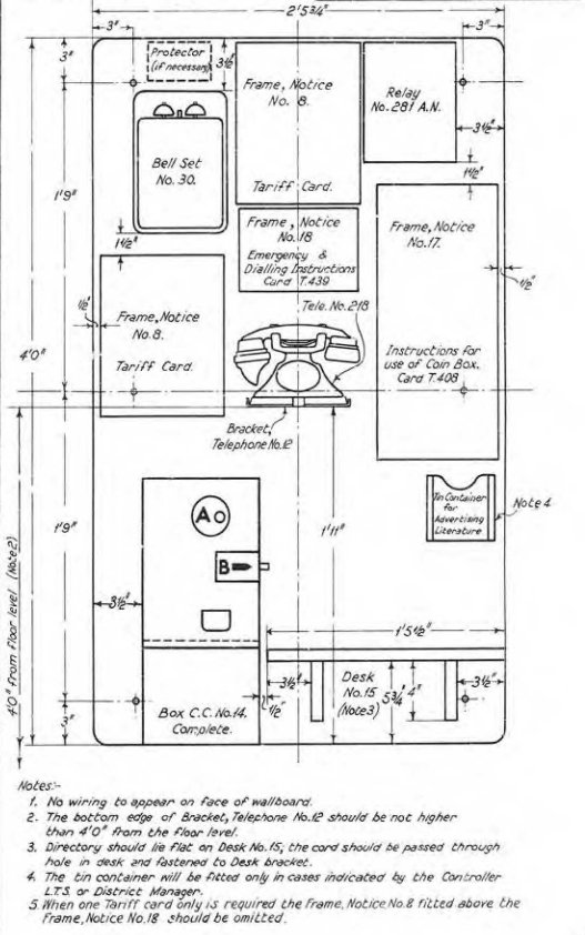
The engineer installing the telephone equipment would be
presented with all the component parts shown in the appropriate drawing.
They would then proceed fit the equipment to the backboard with reference to
the dimensions and layouts in the drawings.
The official title for the backboard itself was "Wallboard
XXinch x XXinch", so the backboard in the picture below would be a Wallboard
53 x 30. Click here for more information.
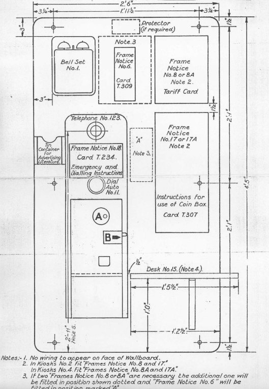
Kiosks No. 2 and 4
Using Box, Coin Collecting No. 13 with Telephone No. 123
Automatic System
Diagram EC 1403 (1930)

Kiosks No. 2 and 4
Using Box, Coin Collecting No. 16B and Telephone No. 196
Magneto System
Diagram EC 1587 (1933) - without battens
Diagram EC 1587 (1933) - with battens

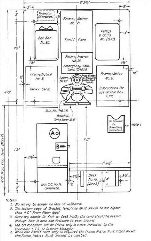
Kiosks No. 2 and 4
Using Box, Coin Collecting No. 14 and Telephone No. 218CB
Manual (CB) System
Diagram EC 1577 (1932)

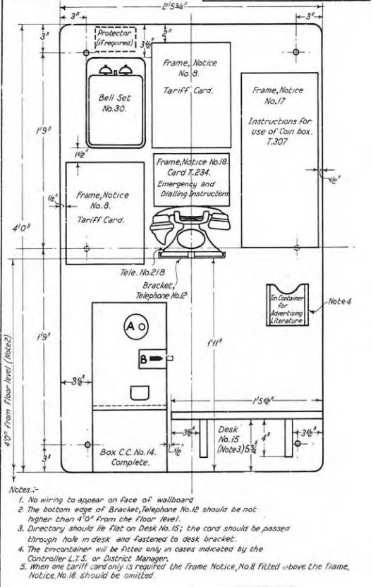
Kiosks No. 2 and 4
Using Box, Coin Collecting No. 14 and Telephone No. 218
Automatic System
Diagram EC 1578 (1932). Superseded by
EC1851
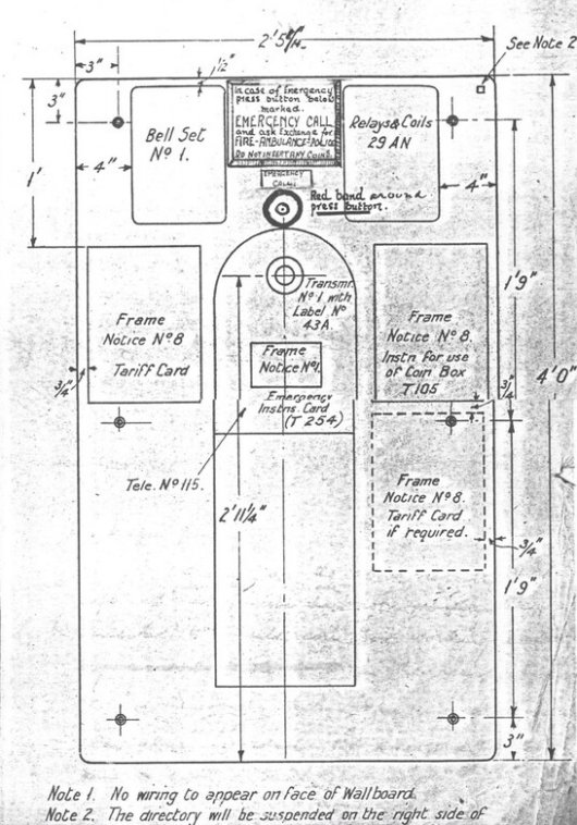
Kiosks No. 1
Using Telephone No. 115
Manual (CB) System
Diagram 2305 (1926)

Kiosks No. 1 and 3
Using Box, Coin Collecting No. 16B and Telephone No. 196
Magneto System
Diagram EC 1588 (1933)
Kiosks No. 1 and 3
Using Box, Coin Collecting No. 14 and Telephone No. 218
CB (Manual) System
Diagram EC 1582 (1951)
Kiosks No. 1 and 3
Using Box, Coin Collecting No. 14 and Telephone No. 218
Automatic System
Diagram EC 1584 (1952). Superseded by
EC1851
Kiosks No. 1 and 3
Using Box, Coin Collecting No. 14 and Telephone No. 218
Rural Automatic System
Diagram EC 1583 (1952) Superseded by
EC1851
|