There were two versions on the MATE system. The
original system was based on the No. 192 telephone, whilst the later was
based on the 700 type telephone and complied with 62-type rack construction.
Click here for the later type -
Key and Lamp Unit No. 1000A
The older
system is described below.
P.O. ENGINEERING DEPT. ENGINEERING INSTRUCTIONS
TRANSMISSION
TELEPHONE
R 1604
Issue l, 19.11.58
MULTIPLE-ACCESS TELEPHONE EQUIPMENT (M.A.T.E.)
Description
1. General
This Instruction describes the Multiple-access Telephone Equipment (M.A.T.E.) which is
being provided for the termination of speaker circuits and exchange lines in the larger
repeater stations.
2. Facilities
Special speaker switchboards or telephones to which all speaker circuits and exchange
lines are connected are provided at selected points in the station. These provide
facilities for calls to be originated or received on any circuit (or exchange line) at any
of the selected points without the intervention of an operator. Microphones, connected to
a loudspeaker system, can be provided at each point so that any officer may be called to
speak on the calling circuit.
3. Incoming calls operate a relay-set which lights a calling lamp on each
switchboard and connects a tone over the loudspeaker system (or operates a station bell at
those stations where a loudspeaker system is not justified). In stations where specific
exchange lines or speaker circuits are allotted to different functional groups, e.g.
audio, carrier, or coaxial maintenance or works orders, and where the lines are shared
between different floors, distinctive tones may be used to indicate the group required.
300, 500 or 800 c/s are normally provided but if these do not give sufficiently distinct
signals other frequencies may be used.
4. Outgoing calls can be originated from any switchboard or telephone, all of
which have facilities for loop calling, loop dialling, 17c/s ringing, balanced battery or v.f. tone signalling. Busy lamps associated with each circuit are provided on all
switchboards and telephones to indicate engaged lines.
5. Equipment
The equipment necessary for a complete installation comprises the following :-
Equipment, Speaker, RP 4633
Panels, Speaker, RP 4634
Switchboards RP 3751, 18/18 or 36/36
Telephones RP 3771
Microphones and loudspeakers.
(NOTE: At certain early installations an
Equipment, Control, was provided in place of the Equipment, Speaker).
The drawings and diagrams for these equipments are given in Table 1.

Switchboard RP3751 with Telephone RP3771
6. Equipment, Speaker, RP 4633
The Equipment, Speaker, RP 4633 comprises a 9 ft. 0 in. or 10 ft. 6 in. Rack,
Apparatus, No. 42.... which accommodates the calling relay-sets (Panel, Speaker, RP 4634),
Oscillators No. 13.... (for calling signals) and loudspeaker-amplifiers.
7. The Panels, Speaker, RP 4634 are fitted on the front of the rack which, when
fully equipped, will accommodate 18 panels (36 circuits). The equipment will normally be
wired for either 9 or 18 panels depending on the size of the station and the number of
panels actually fitted will depend on the number of speaker circuits provided.
8. On the rear of the equipment accommodation is provided for three Oscillators
No. 13...., two loudspeaker-amplifiers, a tone distribution panel and a fuse-mounting and
ringing resistance lamp panel for providing battery and 17 c/s ringing distribution to the
speaker switchboards.
9. Panel, Speaker, RP 4634
Each Panel, Speaker, RP 4634 accommodates two speaker calling circuits which will
operate to 17 c/s or balanced battery signals by appropriate strappings on the panel
connexion strip.
10. The interconnexion of the Panel, Speaker, RP 4634 and Switchboard RP 3751 and
Telephone RP 3771 is described below.
Relay L operates to the incoming 17 c/s or balanced battery, Ll operates relay LL which
locks via LLI and B2; LL2, 3 and 4 (LL2 only shown) extend 1 30V to light calling lamps on
switchboards and LL5 and 6 extend tone to the loudspeaker system. The call is answered by
operating the appropriate speak key on any switchboard or selecting the calling line and
lifting the handset of a Telephone RP 3771 (see par. 14). In each case an earth condition
is returned to the speaker panel to operate relay B. Bl disconnects relay L, B2 releases
the locking circuit of relay LL and B3, 4 and 5 (B3 only shown) extend l3OV to light the
appropriate engaged lamp on all switchboards and any telephones switched to that line.
Relay LL releases and LL2, 3 and 4 break to extinguish the calling lamps. On completion of
the call restoration of the switchboard speak key or replacement of the telephone handset
disconnects the earth to release relay B and the circuit is restored to normal.
TABLE 1
| Equipment |
Schematic |
Wiring |
Assembly |
Cross-connexion |
| Equipment, Speaker, RP 4633 Panel, Speaker, RP 4634 Switchboard RP 3751
Telephone RP 3771 Equipment, Control |
RP 4633 RP 4634 RP 3751 RP 3771 RP 3751 |
RPW 4633
RPW 4634
RPW 3751
RPW 3771
RPW 3751 |
RPA 4634 Drg. 66937 Drg. 66638 Drg. 66627 RPA 3751 |
—
—
RPX 3751
—
— |
11. Switchboard RP3751
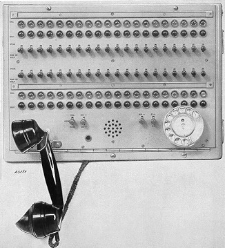 There
are two sizes of switchboard available which accommodate either 18 or 36 lines. Both are
built into metal cabinets suitable for rack, wall or table mounting and their overall
dimensions are 17 in. x 8.75 in. x 4.75 in. and 17 in. x 12.25 in. x 4.75 in. The picture
to the right shows a 40-line switchboard provided on an early installation; the present
36-line switchboard is identical except in the number of lines it accommodates. There
are two sizes of switchboard available which accommodate either 18 or 36 lines. Both are
built into metal cabinets suitable for rack, wall or table mounting and their overall
dimensions are 17 in. x 8.75 in. x 4.75 in. and 17 in. x 12.25 in. x 4.75 in. The picture
to the right shows a 40-line switchboard provided on an early installation; the present
36-line switchboard is identical except in the number of lines it accommodates.
12. Calling and engaged lamps and a speaking and ringing key are associated with
each line. The ringing key is a locking type to simplify the provision of holding
facilities on exchange lines. The lamps used are miniature neons with a current
consumption of approximately 1mA and are operated from the l30V supply. The illumination
from the lamps is not so great as with Lamps No. 2.... but it is found to be adequate
bearing in mind that an audible signal is also given. A switchboard should not however be
placed in such a position that natural lighting will make it difficult to identify a
glowing lamp.
13. Additional non-locking keys provide for the connexion of a dial, 17 c/s
ringing, 300, 500 or 800 c/s tones or balanced battery for outgoing calls. The telephone
circuit is terminated on a Telephone No. 184 via a Jack No. 19 and wiring is provided to
enable the circuit to be extended if required to an additional Jack No. 19. On an
auxiliary test rack (A.T.R.) or other position giving speaking facilities at the equipment
racks. Also built into the switchboard is a moving-coil microphone which is connected
via a key to the input of the loudspeaker-amplifier.
14. Telephone RP 3771
 The
Telephone RP3771, which is shown to the right, provides for the termination of 10 lines
with a single calling lamp and an engaged lamp and gives the same signalling conditions
for outgoing calls as the Switchboard RP 3751. It consists basically of a local-battery
telephone modified by the addition of a special base unit accommodating two rotary
switches, a ringing key and the calling and engaged lamps. The
Telephone RP3771, which is shown to the right, provides for the termination of 10 lines
with a single calling lamp and an engaged lamp and gives the same signalling conditions
for outgoing calls as the Switchboard RP 3751. It consists basically of a local-battery
telephone modified by the addition of a special base unit accommodating two rotary
switches, a ringing key and the calling and engaged lamps.
The 10 lines terminate on one switch so that any line may be connected to the
telephone. The other switch selects the signalling condition to be applied to the ringing
key for outgoing calls.
On receipt of an incoming call an audible signal is received over the loudspeakers (or
the station bell). It is then necessary to search for the calling line by rotating the
first rotary switch until the call lamp glows. Lifting the handset then extends an earth
to the Panel, Speaker, RP 4634 to release the calling condition and light the busy lamps.
15. For outgoing calls the first rotary switch is switched to the required line;
should this be engaged the engaged lamp will glow. If the circuit is disengaged the
second rotary switch is set to the appropriate signalling condition and the ringing key
operated.
16. A microphone for use with the station loudspeaker system is not built into
the Telephone RP 3771 but if required a separate desk microphone can be provided.
17. Loudspeaker arrangements
The loudspeaker-amplifiers, microphones and loudspeakers
are proprietary items manufactured by Messrs. Pamphonic Reproducers Ltd. The
manufacturers’ codes for these items are given in Table 2.
18. These items will only be required in large stations or stations having unusual
layouts or occupying more than one floor. Where loudspeaker facilities are required two
amplifiers should be fitted, one worker and one reserve, the inputs and outputs being
wired via a U-link change-over panel. Each amplifier has two inputs, MIC and GRAM.
The microphones are connected to the MIC input and the GRAM is used for the
calling signal tones. This arrangement allows separate adjustments of the amplifier to
cater for different input levels from the microphones and signalling tones.
19. Power supplies
The power supplies required by the equipment are given in Table 3.
In a station where there are no d.c. supplies a Panel, Power, No. 25A (24V d.c.) should
be provided for relay operation and transmitter battery supplies and a Power Unit RP 3046
(6V a.c. and l30V d.c.) for the Oscillators No. 13 and the calling and engaged lamps.
20. Incoming calls other than 17 c/s or d.c.
As stated in par. 9, the speaker panel will operate to 17 c/s or d.c. (battery)
signals. Various other conditions are met in practice and the
arrangements for other signalling conditions are as follows:-
(a) Loop calling
When an extension telephone is to be connected to the speaker system it should be
connected via Unit, Signalling, No. 7 as shown in Diagram RP/RPW 3664.
(b) Tone calling
When a speaker circuit employs v.f. tone signalling, a Unit, Signalling, No. 3 or No. 18
(for 500 c/s) or a Unit, Signalling, No. 11 (for 300 or 800 c/s) should be provided.
TABLE 2
| Item |
Manufacturers’ code |
Remarks |
| Loudspeaker-amplifier |
No. 600 W/RM |
Type 600 V was provided on early installations |
| Microphone |
No. 948 P |
Built into the switchboard |
| Microphone |
No. 765 S |
For use with telephones and requires a mounting to be constructed locally |
| Loudspeaker |
No. 776 A |
Rack fitting or for suspension from overhead ironwork |
| Loudspeaker |
No. 775 C |
Wall fitting |
TABLE 3
| Supply |
Use |
| 24V or 50 Vd.c. |
Relays on Equipment, Speaker, RP 4633 Transmitter battery on switchboard
and telephones |
| 130V d.c. |
Calling and engaged lamps on switchboards Oscillator anodes |
| 230V a.c |
Loudspeaker-amplifier |
21. Omnibus speaker circuits
The multiple access telephone equipment may be connected to a 4-wire omnibus speaker
circuit either as a terminal or an intermediate station. On circuits employing d.c. code
signalling, d.c. code 1 can be accepted by a terminal station; intermediate stations
cannot receive d.c. code signals but the circuit provides for their repetition. The
circuit arrangement and operation are given in Dgm. RP 4809 and Dgm. Notes RP 4809 for
terminal stations and in Dgms. RP 4810 and RPX 4810 and Dgm. Notes RP 4810 for
intermediate stations.
An article taken from the
Post Office Electrical Engineers
Journal Volume 47 Part 2
(July 1957)
Multiple Access Telephone Equipment for
Repeater Stations
In a large repeater station the number of speaker circuits
required for use during maintenance and construction operations has
necessitated
their termination on an operator-attended speaker rack. Some of the
disadvantages of this arrangement have been overcome in a trial installation
at Bristol repeater station in which provision has been made for multiple
access to speaker circuits from a number of convenient points within the
station. The author describes the equipment giving this facility and
comments on the experience gained in its use.
Introduction
To enable construction and maintenance work on long-distance circuits to be
performed satisfactorily a network of speaker circuits is required for the
use of repeater station staffs. At the larger stations serving many routes
and employing groups of staff on separate and distinct duties, the speedy
distribution of speaker traffic may present difficulties. With the normal
arrangement of terminating such circuits on a speaker rack attended by an
operator, incoming calls must be connected over an extension circuit to the
officer concerned, possibly at the remote end of the station or in another
room; even then, the call may be answered by an officer engaged on some duty
other than that which concerns the caller, in which case shouted
instructions may have to be resorted to.
With this difficulty in mind the South-Western Region suggested, at a
'Headquarters Conference on Maintenance of Repeatered Circuits'' held in
1947, that certain changes in practice should be introduced; and, in
particular, that arrangements should be made to give multiple access to
speaker circuits on panels mounted at various points throughout a repeater
station, with a means of indicating the called party required. This proposal
appeared to have many advantages apart from removing the need for a speaker
rack operator, and it was agreed that a field trial should be carried out in
Bristol 'A' repeater station.
Equipment for this purpose - now known as 'Multiple Access Telephone
Equipment' - was in fact tried out in a simple form after Swindon 'B'
repeater station had been burnt out in 1949. On this occasion service at
Swindon was restored by the installation of four mobile repeater stations
and the Multiple Access Telephone Equipment (M.A.T.E.) proved quite
satisfactory; valuable experience was then gained which helped to determine
a suitable design for the main field-trial installation at Bristol.
Facilities Provided
The main facilities provided by the M.A.T.E. are as follows:-
-
Calls can be originated or received at any access point.
-
Access panels provide for visual and tone (or bell) calling signals; and
for visual engaged signals.
-
Exchange lines and any type of speaker circuit may be connected to an
access-panel key position.
-
'Call-in' facility to attract the attention of a wanted officer from any
access point.
-
Several officers can simultaneously obtain connection to speaker
circuits, via local battery telephone switchboxes, by sharing an access
position.
-
Circuit conditions provide different calling tones to indicate the
officer required to answer a particular call; the tones are broadcast over a
loudspeaker system.
Outline of Equipment and Operation
The main units comprising the M.A.T.E. are the access panel (each
accommodating 20 speaker circuits) and the telephone panel serving one or
more access panels. These circuits, constructed from stock items, are
normally rack-mounted, but where this is not practicable a suitable
wall-mounting is used. Switchboxes to give sharing facilities at access
positions are connected by jumpers to a connection strip at the rear of the
access panel, and a Yaxley switch incorporated in the switchbox permits the
choice of any of 12 speaker circuits.

Fig. 1 - Typical Circuit Termination at M.A.T.E.
A typical circuit termination for the M.A.T.E. is shown in Fig. 1, from
which it will be seen that an incoming call operates relay LL via LI and
lights the associated lamps at each access position. An interrupted tone of
frequency appropriate to the circuit in use is simultaneously
connected to the station loudspeaker via LL2 and the required officer
answers the call at the nearest access panel.
'Call-in' facilities (not shown) are provided on the telephone panel so that
another officer may be brought to the telephone if necessary, by
broadcasting an announcement.
Outgoing calls can be originated from any access panel.
The up side and the down side of a through 4-wire circuit at an intermediate
station would each take a separate access-key position. The keys would be
adjacent and slight wiring changes in the access panels have to be made.
When either of these access keys is operated, a hybrid transformer
terminates the required 4-wire section, speech and signalling then being as
at a terminal station.

Fig. 2 - Wall-Mounted Access and Telephone Panels.
Equipment Details
Access Panels
Fig. 2 shows the face of the access and telephone panels. A label strip runs
along the top edge of each access panel, and immediately beneath this is a
row of lamps with green opals to show the circuits which are in use. Below
these lamps is, firstly, a row of calling lamps, whose opals are so marked
or coloured that an indication is given as to which section of the staff is
wanted, and, secondly, a row of keys. This arrangement allows the operator
to observe quickly which key has to be operated when answering a call, the
designation of the circuit being subsequently given by the glowing of the
busy lamp. The opals used for calling lamps at Bristol are white for
audio-maintenance circuits, white with a black bar for H.F. system
maintenance and red for Works Order duty circuits.
Locking keys have been used so that ringing or hold facilities can be given
on any key position. The calling frequency, other than 17 c/s, to be used on
any circuit is selected by keys on the telephone panel.
Two connection strips are mounted on brackets at the rear of each panel
case. One strip makes common to each key position (a) the 17 c/s supply, (b)
the multi-frequency ringing supply channel from the telephone panel, and (fc)
the 'hold' coil. It is also the terminal point for the signalling or hold
wires from the keys. Thus, by suitable strapping, any one of conditions (a),
(b) and (c) can be connected to a particular key. The other strip carries
the
five incoming circuit wires to each key, i.e., the transmission pair, the
busying, calling-lamp and engaged-lamp wires.
Telephone Panel
Mounted from left to right are (a) a telephone hook, (b) a jack for the
handset telephone, (c) a press-button for switching the telephone to the
loudspeaker system, (d) two keys for selecting the method of calling, and
(e) a dial. Inside the case are the miscellaneous components used in the
speaking circuit. A small connection strip for terminating the incoming
supplies and the loudspeaker circuit is mounted on the rear outside lace of
the
case.
Switchbox
Fig. 3 shows two switchboxes, one open and the other closed. The front
vertical face carries the Yaxley switch and an engaged lamp. The remainder
of the box is hinged to the top of the front face and on its top inclined
surface is mounted a label holder for displaying the designations of the 12
selected circuits together with their switch positions.

Fig. 3 - The Switchboxes
The circuits with power-supply wires are cabled from a
connection strip, to which they have been connected from the access panels,
to a small connection strip on the base of the box. This latter strip also
accommodates the wiring from the switch contacts. The telephone cord
terminates in
the box and is thence wired to the moving-arm terminals of the switch.
Local battery telephones are used in conjunction with the switchboxes so
that speech is possible on 'speaker' circuits. Each telephone is
fitted with a locking press-button key which in its un-operated position
isolates the telephone from the switchbox. Consequently, interference with
busy circuits is avoided either when operating the Yaxley switch or when the
handset might be accidentally removed. A free circuit having been selected
by the switch, the key is depressed, so engaging the circuit and connecting
the telephone to line.
Several of these boxes can be used at one access point. Calling, other
than by dialling, has first to be done from the access panel.
Loudspeaker System
A common amplifier for the loudspeakers would normally have been used, but
at Bristol each loudspeaker has its own amplifier. Tones and speech are
obtained from the 2-wire side of a hybrid transformer fed on one leg of the
4-wire side with calling signals when applied and on the other leg with
speech from the 'call-in" circuits. Two calling-signal tones of 300 c/s, for
Works Order circuits and 500 c/s, for maintenance circuits, are used,
the tones being interrupted by the contacts of a relay energised by 0.5sec.
pulses.
Cabling and Racking
Calling and miscellaneous equipments are cabled to the distribution frame in
accordance with normal practice. Power supplies to access points are
cabled direct from the fuse mountings on the relay and miscellaneous rack,
the rear of the existing speaker racks being used to provide this
miscellaneous rack.
Access panel multiple cabling is taken from the 'local' side of the
distribution frame along both sides of the station. The cable is run on the
underside of existing runways, distribution points being teed-in at
convenient intervals. The connection strips used for the distribution points
are fixed to U-shaped mountings clipped to the runway bearers, and cabling
is taken from these points to access and telephone panels as required. There
are four such appearances along the south side and five along the north side
of the repeater-apparatus room at Bristol, catering at present for nine
access positions.
The lamp wires are limited to five distribution points to avoid overloading
the relay contacts, i.e., calling and engaged-lamp relay contacts each feed
only five appearances.
Three loudspeaker-amplifiers cabled to the distribution frame are dispersed
to advantage about the station.
Access and telephone panels are mounted at the most convenient points, and
to achieve this three types of mounting are used: rack, table and wall. The
table mounting is simply two 'L' shaped pieces of iron strapped together to
form a frame, while the wall mounting is of gate construction to allow easy
access to the rear of the panels (see Fig. 2).
Experience gained from the Field Trial
The trial has shown that during full staffing periods no improvement results
in the speed of answer, and during very busy periods there is a slight
degradation due to the absence of an operator. Excessive delay is prevented
by the officer-in-charge answering any call which does not receive attention
within a reasonable time. During periods of light staffing, however, there
is considerable improvement compared with the use of a speaker bay, the
operator of which would not be in attendance at such times.
As regards effective co-operation, an improvement has been realised, as
anticipated, and the 'call-in' facility is much used, with the loudspeaker
system adjusted to attract immediate attention but without being too
obtrusive.
The time spent in originating calls has also been reduced. Prior to
the field trial, delay was often encountered, resulting in the caller having
to walk to the speaker rack to ascertain the reason. When a required circuit
was engaged, the caller had either to rely on the operator calling him when
the circuit was free and he was available, or make further attempts. The
caller can now see at a glance when a circuit is free.
Conclusions
One of the main advantages of the scheme has been the convenience of being
able to answer calls at any point or room in the station. This is most
advantageous during periods of short staffing and would be so at all times
at any station which has not enjoyed the luxury of a speaker-rack operator.
Another great convenience is the facility of being able to maintain more
than one call at a time, which is especially helpful at test-rack positions.
Formerly, walks between the test and speaker racks became necessary to
ensure co-operation in setting up a second call whilst still retaining
an existing call.
While the trial equipment was in the design stage it was feared that an
officer, when transferring from an access position to a more convenient one,
would omit to restore the speak keys at the first position. This, however,
has not been so in practice.
Interrupted calling-tone signals have been found to be quite effective; a
call bell would have been discordant and would have caused confusion with
alarm bells. It is preferable to keep the volume of the loudspeakers low to
prevent disturbance in the working of the station and consequently it is
essential that an adequate number of loudspeakers be provided.
Prior to the trial it was decided not to use 800 c/s tone for a calling
signal as it was thought that its use might interfere with loudspeaker
monitoring of circuits under test. However, during the trial it became
desirable that the two maintenance groups of circuits should have individual
calling tones. An 800 c/s tone has, therefore, been allotted to the H.F.
maintenance group and 500 c/s is retained for the audio-maintenance group.
One difficulty encountered in designing the field equipment from standard
components was the excessive current taken by the multiplying of calling and
engaged lamps. It is understood that this will be overcome in production
models by the employment of neon lamps.
|