POWER PLANT FOR PMBX'S | |||||||||||||||||||||||
|
In the early days of the telephone industry there was no national grid and very little supply to residencies and businesses. Rural areas were without power due to distribution costs and generally only the towns were covered. To make matters worse, the supply could be D.C. or A.C. with different voltages, dependent on the supplier. This meant that batteries and direct power feeds from the local exchange were in regular use. Where a mains supply was available the Post Office originally supplied two batteries and a "Panel Charging" which would have to be manually switched to allow for charging the redundant batteries. Nationalisation of the electric industry bought stability and also a standardised supply. The Post Office then introduced a single battery that was floated via a rectifier. This bought greater efficiency and a reduction in costs, as only one small battery was used. For customers with low powered apparatus this meant the installation of a battery box and rectifier, or a small cupboard. Very large apparatus involved the installation of a large battery and a big wooden rack, which take up a lot of space. Reliability with the mains supply and technology produced great efficiencies and batteries ceased to be used. Whilst they maintained power in the event of a mains outage, their main task was to smooth the power supply, stopped hum. An extract from A New Power Plant for P.M.B.X's. Up to the present, double battery schemes (charge-discharge working) have been standard for the power supply at P.M.B.X.'s (also HES No. 1 and 2). The author describes the single battery float scheme which will be provided on future installations. Introduction
Where more than one of the above methods is possible, the choice is determined from economic considerations. Excluding the smaller switchboards, the choice usually lies between methods (b) and (c), and generally, supply by means of a power lead proves the cheaper. Where secondary cells are installed it has been the practice to install duplicate batteries worked on a charge-discharge basis. With very few exceptions the cells are charged on the subscriber's premises from the public supply mains or the subscriber's private supply. Economic considerations apart, secondary cell power plants have two important advantages over power leads:-
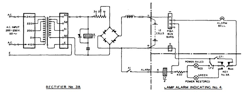
The relatively high cost of secondary cell installations arises partly from the capital and installation cost of the cells and the associated control and charging equipment, and partly from the high maintenance charge. The bulk of the latter charge is caused by the necessity for periodic visits at short intervals to change over the batteries. It was realised that a considerable reduction in these costs might be effected by a properly designed float system. Such a system has now been standardised for the power supply to P.M.B.X.'s. equipped for more than five exchange lines (Switchboard AT3796, etc.) where an A.C. mains supply is available. New Type of Plant The schematic diagram of the new plant is shown in Fig. 1, from which it will be seen that the load is in parallel with a 12-cell battery floated across the mains via a metal rectifier (Rectifier No. 38).
Fig. 1 - CIRCUIT CONNECTIONS Three sizes of rectifier, capable of supplying maximum loads of 15, 30, and 60 Ah per day (denoted by suffix letters A, B and C respectively), have been standardised. For larger loads rectifiers may be connected in parallel. The rectifiers, which have been designed in collaboration with Messrs. Westinghouse Brake & Signal Co. Ltd., consist essentially of a mains transformer and bridge connected rectifier. A choke in the D.C. negative lead provides sufficient smoothing for P.B.X. work. The mains transformer secondary taps and the resistance in the secondary circuit allow for adjustment of output during manufacture. In the smallest size (Rectifier No. 38A) this resistance is also used to provide three different outputs by taps, thus effectively combining three sets in one, viz., a capacity of 5, 10 or 15 Ah per day. The function of the relay connected across the secondary of the mains transformer is to give immediate notification of a failure of the mains supply. The circuit arrangements are described later. Figs. 2 and 3 are photographs of the smallest and largest sizes respectively.
Fig. 2 - RECTIFIER No. 28A Operation of the Rectifier
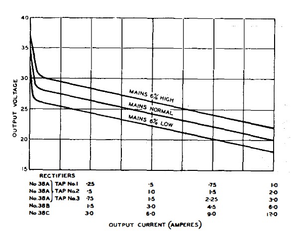
Once installed the operation of the system is entirely automatic. It is evident from the regulation curve of the rectifier that the magnitude of the rectified current depends on the applied mains voltage and the battery voltage, that is to say, one or the other must van if the rectified current is to vary. Now although the load current will often vary considerably from minute to minute as the number of circuits in use at the P.M.B.X. varies these rapid variations of load current may take place without any appreciable change in the battery voltage. Thus the rectified current and the load current may, and usually will, differ considerably in value at any particular instant. When the load current is greater than the rectified current the difference is supplied by the battery, which thus discharging. When the conditions are reversed the excess current delivered from the rectifier is taken up by the battery as a charging current. If the average value of the load current remains consistently greater than the rectified current for a sufficient length of time the resultant discharge from the battery will lower the battery voltage, and the voltage change will increase the rectified current. In the reverse case the rectified current will decrease as the battery voltage rises due to charge. In other words when ever the average value of the load current remains consistently different from the value of the rectified current the battery voltage will vary in such a manner as will tend to equalise them. It will now be apparent that the basis of the system is that the battery acts as a reservoir of power which may be drawn upon during periods of heavy load, the power so borrowed being replaced from the mains supply during periods of light load, and that the battery voltage is the controlling factor. It is thus to be distinguished from the usual arrangement adopted for large single battery power plants, in which the power required by the load, apart from peak loads of short duration, is supplied from the mains as it is required. the battery being maintained at an approximately constant voltage of 2�16volts per cell. The system here described is so designed that the battery voltage will vary, under normal working conditions, from 24 to 30 volts maximum. How these limits are maintained will, perhaps, best be made clear by considering a practical example. Suppose that a switchboard with a day load of 30Ah (calculated at 26volts) is served by a Rectifier, No. 38B. In such an installation the battery capacity would not be less than 50Ah. Experience shows that normally 40 per cent. of the day load is concentrated in the two busy hours. It will be assumed that the other 60 per cent. is totally absorbed in six hours. The actual load delivered during the busy hours, therefore, will be 40 per cent. of 30, that is 12Ah at an average current of 6A. The remaining 18Ah will be delivered in six hours at an average current of 3A. During the busy hours the battery will be discharging and the battery voltage will consequently not be greater than 24V. With nominal mains voltage the output from Rectifier No. 38B at 24V is approximately 3A, as will be seen from the regulation curves, Fig. 4, so that the battery must supply 2 (6-3) = 6Ah. For the remaining six hours the load current and the rectified current will both approximate to 3A and hence it is not likely that there will be any further appreciable drain from the battery. The total drain from the battery during a normal day is thus 6Ah, which will not lower the voltage of a 50Ah battery below 24V.
Fig. 4 - REGULATION CURVES At the end of the working day in this assumed installation the rectified current will be equal to 3A, and the load current will be zero. The battery is now on charge and the battery voltage will rise more or less gradually and, as a consequence, the charging current will be progressively reduced. The battery will continue charging with a rising voltage and a falling charging current until a point is reached at which the rectified current has fallen to a value incapable of causing any further voltage rise. The system will remain stable at this point until either the mains voltage changes or a load is applied. The actual battery voltage at which the system will stabilise under no load conditions is determined by the final charge rate, that is the ratio of the battery capacity to the rectifier output. The maximum current the rectifier can deliver at 30volts may be read off the regulation curve for mains 6 per cent. high, Fig. 4, and is seen to be approximately 0�3A, and thus the maximum charge rate at 30V would be 50/0�3 that is 167. The following typical figures, obtained by test on the Post Office enclosed type cells, show how final battery voltage is related to charge rate:-
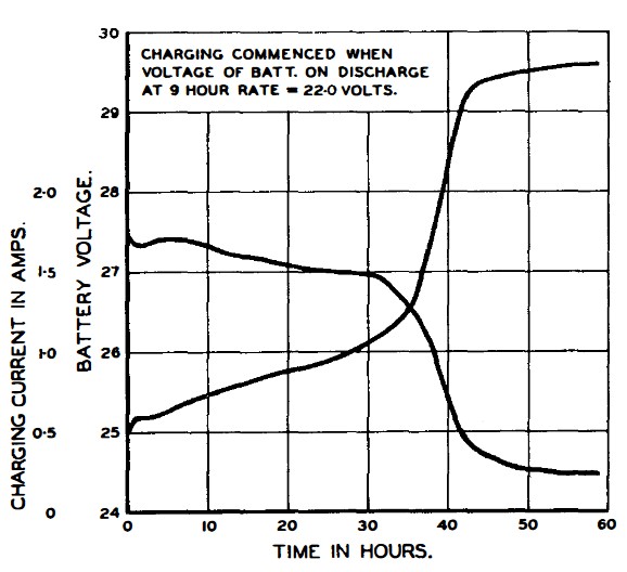
As 167 lies between 200 and 133 in the above table the maximum voltage that will be reached in the assumed installation will lie between 29.5 and 30, and will be reached only when the input mains are 6 per cent. high-quite a likely condition during the night. At these rates gassing is inappreciable and the battery may be left on charge indefinitely. Curves showing the actual rise in battery voltage and decline of charging current with a Rectifier No. 38B connected to a completely discharged 12-cell, 50Ah battery on no load are given in Fig. 5.
FIG. 5 - RISE IN BATTERY VOLTAGE AND DECLINE IN CHARGING CURRENT When the mains supply fails the load will be served solely by the battery. Even if the failure takes place at the end of the working day the example just considered shows that a large fraction of the rated battery capacity will be available. It has been assumed, rather arbitrarily, that the average discharge during the busy hour, under mains failure conditions, should not exceed the 8-hour rate. As already stated it is a good working rule that 20 per cent. of the day load is absorbed during the busy hour, hence, if L is the day load in ampere-hours, the average load current during the busy hour is numerically equal to L/5. If this is not to exceed the 8-hour rate the minimum capacity of the battery must be L/5 x 8, that is l.6L. Thus at whatever time of the day failure of the mains supply occurs there will be at the very least 24 hours reserve of power available in the battery. In the majority of installations there will be more as the capacity of the battery is normally based on the estimated load at the ultimate development period ten or even twenty years ahead. Mains Failure Alarm Accommodation
Fig. 6 - CABINET INCORPORATING RECTIFIER No. 38B, WITH BATTERIES, ETC.
|
|||||||||||||||||||||||
Last revised: July 23, 2025FM |