|
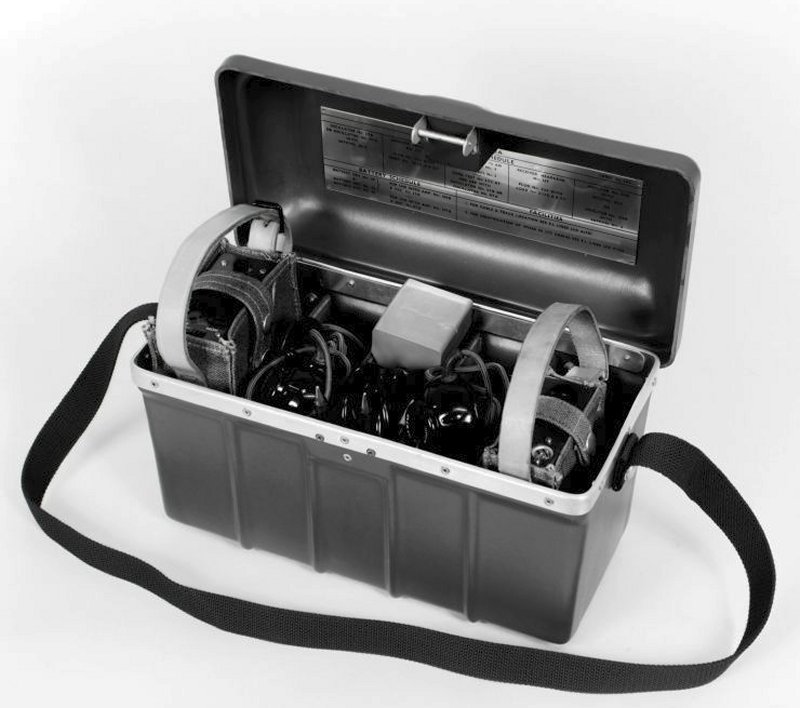
This tester is a kit of parts that are used together for
cable and cable pair identification.
Tester No. 132A includes:-
1 x Case No.
110A.
1 x Amplifier No. 100B or 109B.
1 x Oscillator No. 59B or 87A.
2 x Receiver, Headgear No. 16T.
1 x Cord, Test 2/72AM.
1 x Cord, Test
No. 2/72AT.
2 x Plug No. 420 with Cord No. 2/138AB 54".
1 x Label No.
385.
1 x Probe No. 4.
2 x Probe No. 5.
Satchel No. 3 - For
Amplifier No. 100B, Oscillator No. 59B and No. 87A.
Satchel No. 4 - For
Amplifier No. 109B.
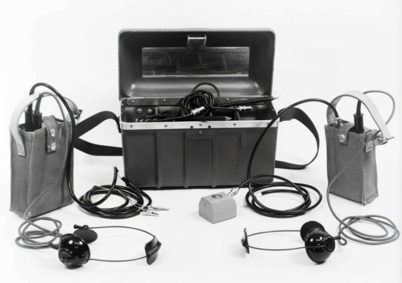
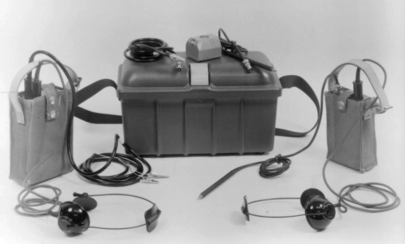
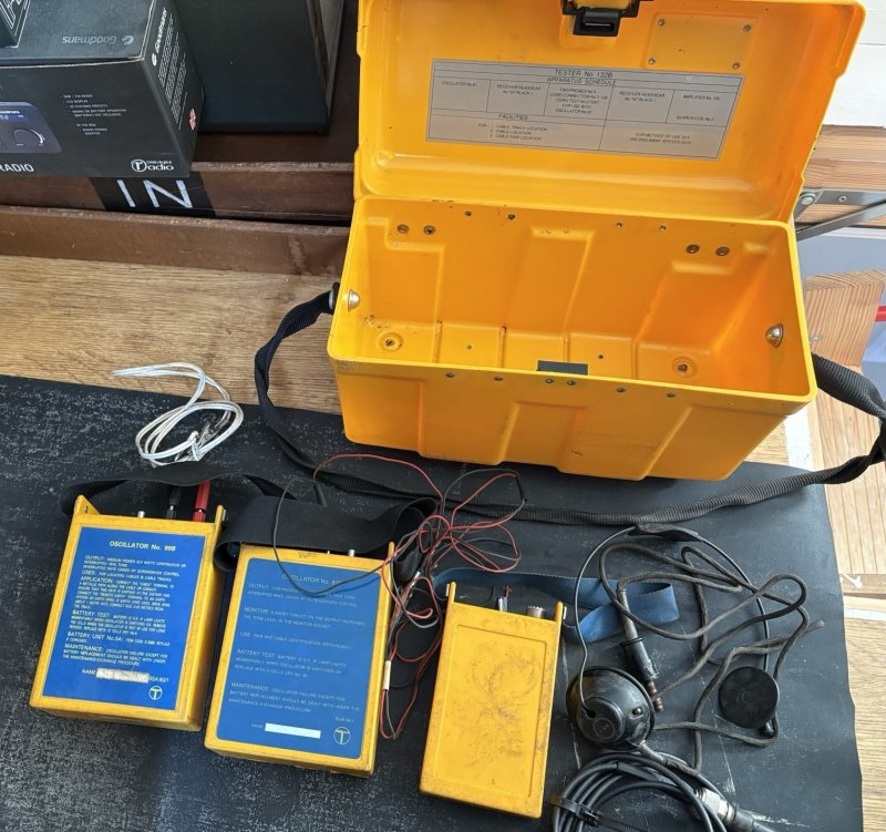
Tester No. 132B includes:-
1 x Case No.
110A.
1 x Amplifier No. 109B.
1 x Oscillator No. 87B.
2 x Receiver,
Headgear No. 16T.
1 x Cord, Test 2/72AM (used with Probe No. 4).
1 x Cord, Test No. 2/72AT.
2 x Plug No. 420 with Cord No. 2/138AB 54".
1 x Label No. 385A.
1 x
Probe No. 4.
2 x Probe No. 5.
1 x Satchel No. 4 - For Amplifier No.
109B.
1 x Satchel No. 3A - For Oscillator No. 87B.
TI A2 A1001 - Description
TI A2 A1003 - Identification of cable
pairs
Tester No. 132C -
User Guide
Tester No. 132K - User Guide
Tester No. 132A
Tester No. 132A
Tester No. 132A
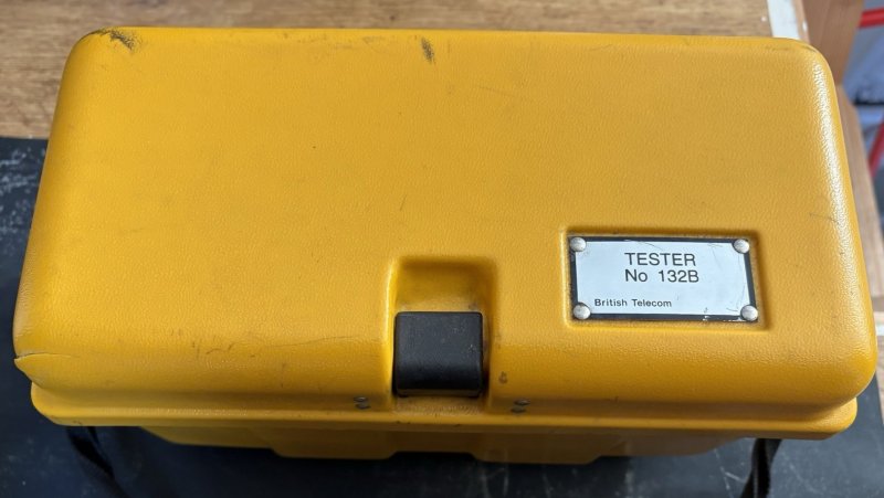
Tester No. 132B
Tester No. 132B

Tester No. 132B
Tester No. 132C
TESTER No. 132C
Operating Instructions
Index
1. General Description
2. Description of Equipment Items
3. Principle of Operation
4. Using the Oscillator No. 87G
5. Using the Amplifier No. 109H
6. Care and Maintenance of the Tester
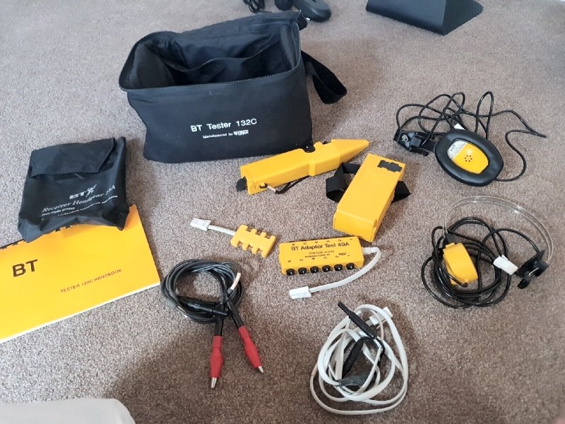
1. General Description
a. Oscillator No. 87G
b. Amplifier No. 109H
c. Receiver Headgear No. 17A
d. Receiver Headgear No. 18A
e. Adapter Test No. 18A
f. Cord Connecting No. 2/26A
g. A storage/carrying satchel
h. This handbook
The powered items (Oscillators and Amplifier) are primary cell battery
operated units.
The Tester No. 132C enables cable pairs to be identified quickly in BT local
networks, provided that the pairs are in good electrical condition.
Where insulation resistance is low or where pairs are subject to short
circuits, contacts or disconnections, location and identification may be
more difficult.
The equipment must only be used in the manner and purpose specified in this
handbook or approved documentation.
No unapproved modifications are to be made to this equipment.
2. Description of the Equipment Items
2.1 OSCILLATOR 87G
General
The signal output is provided via two 4mm sockets enabling the use of
standard leads. A monitor socket is provided to enable connection of a
suitable headphone (Receiver Headgear No. 17A or equivalent).
The Oscillator provides a kHz signal output to line. This signal may be
continuous, or interrupted at between 2 and 10 pulses. The output is set by
a single rotary control.
If desired, the output signal can be monitored whilst the rate is being set.
This is achieved by listening to a headphone connected to the monitor socket
and with the output sockets shortened (looped) together.
DETECTION OF LINE STATUS
The monitor headphones provide an indication of a satisfactory line
connection and also of temporary shorting of the connected line.
When the Oscillator is sending a signal to line, a low level signal will be
heard in the headphone. The headphone output level will rise briefly (for
approximately 3 seconds) when the line is shorted along it's length. The
`SHORT' indicator will illuminate during this period. The `short' condition
may also be indicated when the line connection is first made. The indication
will depend on the line length and the Oscillator model.
NOTE :
a) When the pair is shorter than 100 metres, the indication of line presence
may not operate reliably.
b) When the pair is longer than 2.5 kilometres, the shorting conditions will
not operate reliably.
BATTERY STATE INDICATION
A battery state indicator lamp (`BATTERY') is provided on the Oscillator.
When the Oscillator is on, this indicator will flash at approximately at 2
second intervals. This signifies that the battery voltage is adequate.
If the voltage falls to a level such that the battery requires replacement,
the indicator will flash at a faster rate (typically 7 times a second). In
addition, the signal output to line will change. This will give an
indication to the Amplifier operator that Oscillator battery failure is
imminent (typically half an hour after the output signal changes). The
output signal change takes the form of a long periodic interrupt, i.e. It
turns on and off at two second intervals.
CONNECTION LEADS
The oscillator comes complete with a set of connection leads and clips.
Alternatively, Cords Test 1/500A and Clips Test 38A may be used.
IMPORTANT SAFETY NOTICE
The monitor (headphone) output is only suitable for use with Receivers
Headgear No's 18A or 18A and Headsets No's 7A or 8A. Use of other headphones
may result in the users audio exposure exceeding safety limits.
2.2 AMPLIFIER No. 109H
GENERAL
The amplifier has an integral probe and a loudspeaker output. As the
amplifier probe tip approaches the cable pair which the oscillator signal is
connected to, the clicks generated by the speaker become more frequent. This
enables the pair to be located even when high background noise levels exist.
A rotary sensitivity (gain) control is provided so that the Amplifier may be
adjusted to suit the signal levels being detected.
BATTERY STATE INDICATION
When the Amplifier is switched on or off, the red indicator light will flash
once. This indicates that the battery voltage is adequate.
If the voltage falls below an acceptable level, the light will be on
continuously. The battery must then be changed.
HEADPHONE SOCKET
The output socket at the rear of the Amplifier allows the connection of a
headphone (Receiver Headgear No. 17A or equivalent).
Only the received 1kHz signal is provided to the headphone output. The click
rate signal and the loudspeaker output are disabled when the headphone is
plugged in.
The headphone output system should be used when working in quiet areas on
customers premises, or where interfering signals from other sources are
present on the pair being traced.
IMPORTANT SAFETY NOTICE
The headset is only suitable for use with Receivers Headgear No's 17A or 18A
and Headsets No's 7A or 8A. Use of other headphones may result in the
users audio exposure exceeding safe limits.
2.3 RECEIVER HEADGEAR No. 17A
This the `standard' headphone for use with the Amplifier or Oscillator.
2.4 RECEIVER HEADGEAR No. 18A
This headphone is designed for use with Helmets Safety.
2.5 ADAPTER TEST No. 49A
The adapter plugs into the customers' line jack unit to enable test access
to all six connections. The adapter is numbered to correspond with the
numbered rear wire connections of the line jack unit.
2.6 CORD CONNECTING No. 2/26A
The cord is provided for connecting between either the Amplifier of
Oscillator and a Telephone 286. This enables the telephone headset to be
used for communication and tone tracing.
3. PRINCIPLE OF OPERATION
GENERAL
The Oscillator provides a 1kHz signal which is connected to the pair of
wires to be traced or identified. The signal power is limited to 20mW. To
minimise interference to adjacent lines a sine wave is used.
The signal sets up electromagnetic and electrostatic fields in the vicinity
of, and along the length of the pair. These fields can be detected by means
of either an electromagnetic or electrostatic probe. The signal for these
probes is then amplified and presented to the user through either a loud
speaker or a headphone (receiver Headgear No. 17A or equivalent).
Induction of the 1kHz signal into adjacent pairs balances itself out
giving
negligible crosstalk (interference) to working circuits.
ELECTROMAGNETIC DETECTION
Where a magnetic detection system is required (usually only necessary where
identification of a cable is required) the Tester No. 453A is used. This is
used in conjunction with the Oscillator 87, provided as part of the Tester
No. 132C.
Principles of magnetic detection and the use of the
Tester No. 453A are detailed in the users handbook with the Tester No. 453A.
ELECTROSTATIC DETECTION
The Tester No. 132C provides the 1kHz Oscillator and an electrostatic
detection system.
he electrostatic method is employed for the locating and identification of
individual cable pairs. For electrostatic detection the oscillator signal is
connected directly across the cable pair to be identified or located. If
possible, the pair should be open circuit to ensure the highest signal
voltage at the detection point.
The Amplifier 109H detects the electric field resulting from the voltage
across the pair. For maximum flexibility, two output systems have been
incorporated into the amplifier.
The loudspeaker control is the `normally' used system.
This is built into the Amplifier. The level of the signal detected by the
probe is represented by a variable click rate (pitch) output from the
loudspeaker. The closer the probe is to the desired pair, the higher the
click rate of the output from the loudspeaker.
The alternative to this system is the headphone output. This enables the
user to listen to the signal being radiated by the pair being traced. The
closer the Amplifier is held to the pair, the louder the sound output will
be from the headphone.
4. USING THE OSCILLATOR 87G
The oscillator is connected to the pair to be traced at a convenient point,
typically at a flexibility point such as an exchange frame or a street
cabinet.
To prevent interference to customer service, care must be taken to avoid
connecting the oscillator to working circuits.
Plug the connecting leads supplied into the output sockets of the
oscillator.
Switch the Oscillator on and connect the leads to A and B
wires of the cable pair to be traced using the appropriate test clips or
adaptors. (As the connection is made the `SHORT' indicator on the top of the
Oscillator may illuminate briefly).
If a headphone is connected, satisfactory connection to line is indicated by
a low level tone (the tone may be at the higher `short' indication level for
a brief period after initial connection).
Adjust the Oscillator output to give an interrupted or continuous tone as
required.
Always replace the headphone socket sealing plug when the headphone is not
connected.
The Oscillator must not be connected between earth and the wires as this
will increase the level of tone induced into other pairs. This will also
make positive tracing and identification of the pair difficult and could
result with interference with communications traffic on the cable.
The Adaptor Test No. 49A supplied with the Tester No. 132C ensures the
Oscillator to be connected to a Line Jack Unit. Other adaptors are often
provided with frame and cabinet block systems for test access purpose. These
should be used, where available, to ensure a reliable connection to the pair
to be traced.
Connection to a `live' exchange line will reduce the signal available on the
line and may make the tracing operation more difficult. If practical, where
the Oscillator is connected at an exchange frame, the exchange connection
should be removed by the approved method for the type of block being used,
i.e. insertion of the appropriate wedge or removal of the line fuses.
5. USING THE AMPLIFIER No. 109H
5.1 LOCATION OF A PAIR AT A CABINET (OR PILLAR)
One press of the `ON' switch turns the Amplifier on. The loudspeaker output
will emit two short `clicks' every second, even when no signal is being
received by the probe.
A further press of the switch turns the amplifier off.
Initially, set the sensitivity control to it's mid point. Move the amplifier
over the terminal strips where the wanted pair is expected to be.
If the click rate of the amplifier does not change, turn the sensitivity
control toward its `FAR' setting and repeat the search.
If the click rate does not increase at any point, then the rest of the
cabinet should be searched with the Amplifier until the approximate location
of the pair is found.
The sensitivity control is then turned towards it's `NEAR' setting until
sufficient discrimination is available to enable accurate location of the
pair.
If the identification is in doubt, this may be confirmed by shorting the
wires if the identified pair together - when this is done the click rate of
the Amplifier will drop significantly if the pair is the correct one.
Where applicable, metallic contact must be made by use of the appropriate
test clips or adaptors. The exact method employed will depend on the type of
cross connection system fitted in the cabinet. On no account is contact to,
or shorting out of, the pair to be achieved by cutting into cable insulation
with knives or other insulation piercing devices.
It should be noted that the Amplifier discrimination will always be better
between pair if the sensitivity setting is kept as low as possible, i.e.
close to the `NEAR' setting.
5.2 LOCATION OF A PAIR AT A DISTRIBUTION POINT (DP)
For pair location at a DP the Amplifier sensitivity control will normally
need to be set close to the `NEAR' setting. Location is usually so positive
that shoring out the pair is unnecessary.
5.3 LOCATION OF A PAIR IN A CABLE JOINT
To find a pair within a joint the Amplifier sensitivity should be adjusted
such that an increase in click rate is achieved when the amplifier probe is
close to the joint. Search of the units of the joint to identify the unit
containing the wanted pair. When this has been located, the sensitivity is
further reduced (turn the control towards the `NEAR' setting) to allow the
individual pair to be found.
Maximum click rate will be achieved when the probe is adjacent to the `A' or
`B' wire with a drop in click rate noted when the probe is placed between
the two wires.
If more positive identification is needed, the located pair can be shorted
out to confirm the identification. Ensure that the pair is correctly
reinstated using approved practice.
5.4 CABLE CHANGEOVER OPERATIONS
The use of the Amplifier is as described for the location of pairs in a
joint.
When the Amplifier operator shorts to verify the location, the operator at
the Oscillator end will receive an indication of this (see section 2.1 -
DETECTION OF LINE STATUS). This will indicate correct location of the pair
to both users.
The Oscillator monitor output and/or the Amplifier headphone output may be
fed into the `AUX' input of the Telephones No. 286 being used to communicate
between the two operators. The Cord, Connecting No. 2/26A is used to make
the connection.
This facility connects the Oscillator monitor output or the Amplifier
headphone output to the receiver of the Telephone. This enables the
telephone headset to be used for communication and tone tracing.
6. CARE AND MAINTENANCE OF THE TESTER
The Tester 132C and it's component parts are designed for use in an external
engineering environment. When the Tester is not in use, additional
protection is provided by the storage pouches and carrying satchel.
he headphone socket sealing plug forms an important seal against the
ingress of moisture. Always replace the headphone socket sealing plug when
the headphone is not connected.
he only routine maintenance required is to keep items forming the Tester
as clean and dry as is practical. If cleaning is necessary, a cloth
moistened with a warm, mild detergent solution should be used.
It is particularly important that spent batteries are removed from the
Amplifier and Oscillator. Only manganese alkaline batteries are to be used
in this items, i.e. LR6 for the Oscillator No. 87G, 6LR61 (6LF22) and for
the Amplifier No. 109H.
Note: it is possible to trace a cable pair without the use of an
Oscillator.. the test service 176 can be used for a local number and
will apply a trace tone to the number you enter after 176 (full national
code must be used). To check for correct line, then apply a ground of 2kms
thru the cable pair, if the correct line has been identified then the user
dialling 176 will receive the NU tone (continuous tone). Whilst this service
is in use, no one may dial the subscribers line as it would be busied out.
|