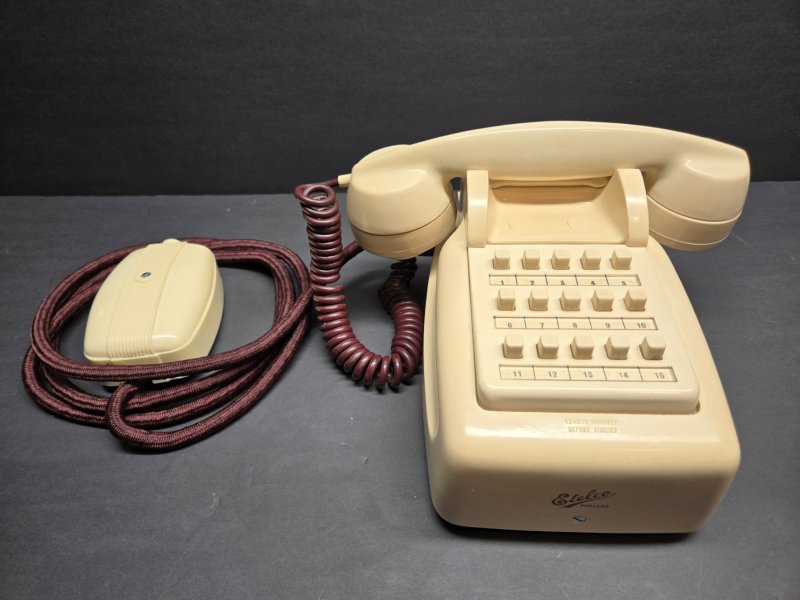
C.B. Intercommunication Telephones
AUTO-RESET, PUSH BUTTON SELECTOR TYPE
 |
|
 |
| N 1636C Type |
|
N 1637C Type |
One of the most effective means of inter-office communication where a relatively small
number of lines is required, is the intercommunication telephone system, as immediate
connection is established on the pressure of a button; no operator or automatic dial
being necessary. It may also be installed in large establishments as a supplementary
system for the use of executives.
For many years our intercom telephones have been markedly popular by reason of their
efficiency and reliability. In conformity with our progressive policy, we have redesigned
these telephones on lines more in keeping with current requirements, and we are confident
that they will have instant appeal, as they embody the simplicity of outline favoured for
the modern office, while still retaining the proved advantages of their predecessors.
The instruments have moulded cases in fadeless black or ivory, and ivory moulded push
buttons; thus, as there are no external metal parts to become tarnished, a lasting
"new" appearance is ensured.
The casing is loose-hinged, and fastened by one screw, to a strong plastic base plate
carrying the internal components which are therefore accessible for maintenance when the.
case is lifted off.
These components include the push button mechanisms mounted in pre-wired units of five,
each unit bearing a paper strip printed with the appropriate numbers. The mechanisms are
protected by a moulded panel having apertures for the buttons and designation strips, the
latter being covered by convex transparent plastic windows which are bonded in and give
prominence to the printed numbers.
Highly satisfactory reproduction of speech is given by the inset transmitter and
electromagnetic receiver incorporated in the moulded micro-telephone, the cord from which
enters the case through a rubber protector arranged to accommodate also the desk cord of
the table instrument.
A moulded desk terminal block is supplied for the connection of the line wires to the
table set, whilst the wires to the wall set enter through a hole in the baseplate and are
connected to screw terminals. A combined instruction/directory card is supplied with each
telephone.
OPERATION
To make a call, lift the micro-telephone and press the appropriate button to its full
extent. If the called number is free, a buzzing tone will be heard in the receiver,
indicating that the required person is being called.
A button, having been pressed, is retained in an intermediate position during the call,
and is automatically released when the micro-telephone is replaced or another button is
pressed; successive calls can therefore be made without replacing the micro-telephone.
Incoming calls operate a buzzer in the instrument. To reply, it is necessary only to
lift the micro-telephone and speak.
POWER SUPPLY
The system is operated from a central battery, or via an eliminator when an a.c. supply is
available. In either case, the best results are obtained when the source of supply is as
near as possible to the centre of the system.
For a maximum line length of 2,000 feet (the approximate economic limit) a battery of
nine dry or inert cells is usually adequate. Where the distance is less, the battery is
proportionately smaller.
REMOTE STATIONS
If a station is remote from the main installation, an N1112A type call and reply telephone
is usually supplied as a subsidiary to the nearest intercom station. The call and reply
telephone can be rung from any station but can only call the one to which it is
subsidiary. This arrangement effects a considerable saving in cable costs.
INSTALLATION
For a complete installation, junction boxes, cells with boxes (or an eliminator) and cable
are supplied.
The type of cable recommended for a particular installation is specified in the
quotation and comprises suitably insulated 9, 14 or 19, No. 23 s.w.g. copper conductors,
respectively, for the 5, 10 or 15-line systems.
| Code No. |
Type |
No. of Lines |
| N1636A |
Table |
5 |
| N1636B |
Table |
10 |
| N1636C |
Table |
15 |
| N1637A |
Wall |
5 |
| N1637B |
Wall |
10 |
| N1637C |
Wall |
15 |
Dimensions (excluding handset): 6.5" x 8.75" x 4.1" (168 x 222 x 105 mm)
Total weight: 4.6lb. (2.1kg.) max.
Note - Orders for telephones should specify the Type No. and colour; black or ivory.
Taken from the Ericsson (ETL) Telephone Catalogue, edition No. 49
The block terminal is a Part N3196 and would colour match the telephone.
Introduced around 1953 and made obsolete in
1971, when they were superseded by the N1620 - N1627
range or small PAX systems.
ETL supplied the Radio Corporation of
America with some of these telephones.
Also supplied to the British Post Office - see
House Telephone System No. 1.
Known models
N1636C10 - 15 way, ivory coloured, table
telephone.
MAINTENANCE INSTRUCTIONS
INTERCOM TELEPHONES TYPES N1636, N1637, N1732 & N1733
These instructions cover:-
1.1 General Maintenance.
2.1 Adjustment of push-button keys.
2.2 Adjustment of cradle switch.
Part Numbers referred to are shown on the relevant equipment drawings.
1.1 GENERAL MAINTENANCE
The simplicity of construction and operation of these telephones, coupled with
the fact that the materials used are not liable to corrosion or excessive wear,
ensure long, reliable service with minimum attention. The instruments are
subjected to stringent tests in the factory and, provided that they are treated
with reasonable care, should require no routine maintenance apart from a
periodic check of the associated batteries to ensure that the output is
satisfactory.
Experience has shown that while these telephones are working efficiently they
are best left undisturbed.
The majority of faults which occur have been found attributable either to the
deterioration of batteries or to low insulation of the cable brought about
during structural alterations or through some building fault, therefore these
possibilities should first be investigated, unless the source of the trouble is
obvious, e.g. a sticking push-button or cradle switch plunger.
However, these are unlikely contingencies in the reasonably dust-free
atmosphere of the average office. In order to cover every eventuality, the
following information for the adjustment of push-button keys and cradle switch
springs has been extracted from our factory specification.
2.1 ADJUSTMENT OF PUSH-BUTTON KEYS
Relevant Drawings:
For Telephones N1636 or N1637, Drawing N78795.
For Telephones N1732 or N1733, Drawings N78793 (or N78794) and N78795.
- All screws should be tight. Screw, part 28, to be sealed with Araldite
to part 21.
- In latched position, each plunger should be free to move slightly before
lifting latch plate 8.
- The plunger should freely lift latch plate from the latched position to
a position not more than .048 in. from edge of frame (see Fig. 1).
- Apply alcohol dag along inside and outside faces of latch plate, on
linking arm, on inside edge of moulded plunger insert and on ends of pin 6.
- Tension of spiral spring 7 should hold short arm firmly against, but not
projecting above, edge of plate 4.
Spring Tensions
Note:- The part must not move when gauge is set at the specified low limit, but
should begin moving at any tension above this, up to the high limit.
- Plunger Springs. With plunger fully depressed, tension at tip of springs
14 and 15 should be 60-80gms.
- Latch Plate Spring (Fig.2). With plungers un-operated and gauge tip
applied to bottom of linking arm, the tension on latch plate 8 should be 3
0-50gms. With any plunger operated (latched) and gauge applied as above,
latch plate must not lift from plunger at less than 100gms pressure.
- Master Station Springset. Tension of all moving springs against back
spring should be 20-30gms measured at tip. Contact clearance:- .010in.
minimum. Moving springs must make contact on operation and have
visible "follow".

2.2 ADJUSTMENT OF CRADLE SWITCH
Relevant Drawing, N82934.
- All screws should be tight. Screws 19 and 16 fixing cradle brackets and
latch spring to be sealed with Araldite at screw end.
- Bracket part 7 should Latch behind latch 5 before 'ringing" position is
reached. Bracket 8 should release 7 before full depression. All movements
should be free.
- Bracket parts 13 and 14 should move freely over pins in bracket part 8.
- Alcohol dag to be applied to all bearing surfaces, particularly parts 1,
5, 11, 13 and 14.
- Brackets 13 and 14 to be square against frame when held in vertical
position by spring 10.
Spring Tensions
Note:- The parts mentioned in (a), (b) and (c) must be free, to ensure true
reading of tensions.
- With latch plate 5 held disengaged from inner bracket 7, tension exerted
by return spring 9 should be such that 65-75gms pressure applied to bracket
7 immediately adjacent to plunger is necessary just to move bracket.
- With springset3 removed and bracket 7 fully depressed a force of 50-60gms applied adjacent to plunger should be necessary to press down bracket 8.
- With bracket 7 fully depressed, tension of latch plate spring 6 should
require a force of 10-15gms applied to tip of latch plate 5 just to move it
away from bracket.
- Locating screws of switch parts 3 and 4 to be varnish sealed during
final adjustment. Locating buffer must be within .005 in. of plate.
Springset Tensions (see Fig. 3)
- With cradle bracket 8 fully depressed, buffer springs 5 and 8 should
exert a pressure of 20-35gms on springs 4 and 7 respectively, with visible
"follow".. Contact gaps between springs 3 and 4 should be .010 -.025in.
- With all plungers disengaged from springset, contact gap between springs
1 and 2 should be .010 - .020 in., and roller springs 4 and 7 should exert a
pressure of 20-35gms on buffer springs 3 and 6, measured at the contacts.
- Actions (a), and (b) above, will automatically ensure correct gap of
.008 - .020in. between contacts of springs 4&5 and 7&8.
- With cradle brackets depressed to within .072in. of their full travel,
all springs of the main springset should be operating.
Ringing springs
- With part 7 latched in the "conversational" position, spring 10 shall be
adjusted so that the contact gap between springs 9 and 10 is .005 - .010in.
with spring 9 tensioned against ringing plunger. This will result in visible
"follow" on spring 10 when part 7 is in ringing position.
- With cradle brackets in the "handset off" position, spring 9 adjustment
should provide for a contact gap of .010 - .025in. between springs 9 and
10.

|
 ERICSSON