| Made by GEC - Click here to go to the GEC
Planset page Prototype pictures of the wall model -
includes pictures of the wall mounting bracket
Main Telephone users guide
Planphone A
Planset N625 table model
How to wire to the UK Plug and Socket system
Introduced circa 1965.
TELECOMMUNICATIONS INSTRUCTION
C MARKETING INSTALLATION
3 Internal
C0020
Issue 4, Jan 1978
EXTENSION PLANS
105, 105A, 107 AND 107A
INTRODUCTION
This Instruction describes Extension Plans 105, 105A, 107 and 107A and outlines their
application and installation using Planphone A, Plan-Sets N625 Table and Plan-Sets N625
Wall.
DESCRIPTION
These extension plans use a Main telephone and one or two extension telephones - see TI C3
C0010 for combination of extension plans.
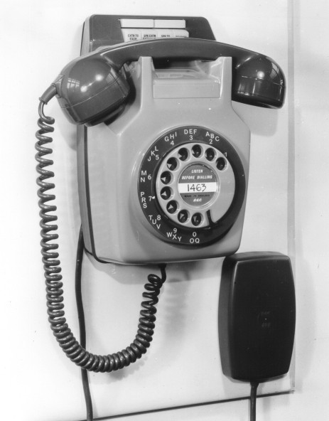
The Main telephone has piano type control keys. There are Table and Wall models, each
available in black, grey or ivory. The 10volt d.c. supply for signalling and transmission is
normally obtained from the a.c. mains supply by means of a
Power-unit No. 53B. If no mains
supply is available, eight Cells, Dry, R40 in a Box Battery, No. 10 may be fitted.
 The Table model is available complete as
Planphone A, pre-wired to Diagram N 628 - see Vocabulary of Engineering Stores. The field
of use of the Planphone A is given in TI C3 C0025. The table model can also be made up
using a Telephone No. 706, 710 or 746 and a Plan-Set N625 Table. A Telephone No. 740 need
never be used on a Plan-Set as the Telephone No. 746 can accept the necessary auxiliary
gravity-switches for the most complex arrangement. The Table model is available complete as
Planphone A, pre-wired to Diagram N 628 - see Vocabulary of Engineering Stores. The field
of use of the Planphone A is given in TI C3 C0025. The table model can also be made up
using a Telephone No. 706, 710 or 746 and a Plan-Set N625 Table. A Telephone No. 740 need
never be used on a Plan-Set as the Telephone No. 746 can accept the necessary auxiliary
gravity-switches for the most complex arrangement.
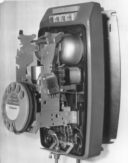
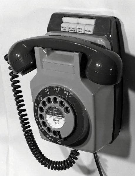
The Wall model must be made up using a Telephone No. 711 or 741 and a Plan-Set N625
Wall. When the complete model has been fixed to the wall access to the Plan-Set terminals
is gained by pressing the slide bar (which is between the wall and the Plan-Set near the
top left corner) with the blade of a screwdriver and moving the Plan-Set body to the right
until the studs disengage and allow it to swing open. It is closed by swinging it shut,
sliding it to the left and pressing the left hand side to lock the slide bar.
The Extension telephones are 700-type fitted with one or more press buttons.
OPERATION
The switching is by means of the four piano type control keys on the Main. Three of the
keys are inter-locking and achieve the following functions:-
The fourth key is non-locking and releases any locked key to establish the 'Main to
extension' condition.
A white lamp is associated with the EXTENSION TO EXCHANGE key and a red lamp with the
SPEAK TO EXTENSION EXCHANGE HELD key. On the table model the lamps glow through lenses
behind the keys; on the wall model the lamps glow through the keys which are translucent.
The white lamp glows while the EXTENSION TO EXCHANGE key is depressed and the extension
handset is off the rest; the red lamp glows while the SPEAK TO EXTENSION EXCHANGE HELD key
is depressed and the handset at the main is off the rest, indicating that an exchange line
call is being held.
Signalling from the Main to the extensions is by means of the two non-locking keys
below the four switching keys. Signalling from the extensions is by means of a non-locking
button on each extension telephone.
FACILITIES
See also the Facility Diagrams, N 1450 and N 1451.
Extension Plan 105
is a Main telephone and two extensions. Exchange calls from the Main
cannot be heard at the extensions. Exchange calls from an extension can be heard at the
other two telephones.
Extension Plan 105A is a Main telephone and two extensions. Exchange calls from the
Main cannot be heard at the extensions. Exchange calls from an extension can be heard at
the other extension but not at the Main.
Extension Plan 107
is a Main telephone and one extension. Exchange calls from the Main
cannot be heard at the extension but exchange calls from the extension can be heard at the
Main.
Extension Plan 107A is a Main telephone and one extension. Exchange calls cannot be
heard at the other telephone.
Intercommunication is possible between Main and extensions and calling is by key at the
Main and press button at the extensions.
Intercommunication is possible between extensions on Plans 105 or 105A. Internal
extensions can call each other directly by buzzer. The assistance of the Main is needed to
establish calls between external extensions.
Incoming calls ring bells except that, when the exchange line is switched to an
external extension a buzzer sounds at the Main. On Plans 107 and 107A only, it is possible
to arrange for the bell at the Main to ring in parallel with the extension bell if the
customer prefers this to the buzzer. The buzzer may similarly be rendered inoperative if
the customer requires that an audible signal should not be given at the Main when the
exchange line is switched to the extension.
On a Plan 105 or 105A with internal extensions an additional press-button and switch
may be fitted in one extension to render the bell inoperative if the customer requires
that only one extension shall be rung on night service.
LIMITATIONS
If one internal and one external extension are called for on Plan 105 or 105A,
they must both be wired as external extensions.
The plan-set is suitable for use on CB and automatic systems only.
External extensions cannot be provided on shared-service exchange line because it would
not be possible for the equipment at the main to distinguish between the 'call main' and
'call exchange' signals. For the same reason an external extension cannot be fitted when
the main is connected on the non-multiple station of a House Exchange System No. 3.
If the plan-set is connected to a PBX, external extensions from the main cannot be
provided. because it is not possible to ensure that ringing and battery will be connected
to the same wire. This is essential if correct signalling is to be provided between main
and extension. Further, it would not be possible for the main to distinguish between 'call
main' and 'recall switchboard' signals.
CONSTRUCTION
Using Plan-Set N625 Table
The plan-set is supplied complete with cord and terminal block and three screws for
attachment to the base of the Telephone No. 706, 710 or 746. The four rubber feet must be
removed from the base of the telephone and the four knockouts (three small circles for the
screws and the elongated hole for the interconnecting cord) must be punched out. Some
telephones with a metal baseplate may have the knockouts already removed, otherwise remove
the printed wiring chassis by withdrawing the two screws at the feet of the gravity switch
and loosening the two screws adjacent to the bell. The interconnecting cord from the
plan-set should be passed through the large hole and the telephone attached to the
plan-set by the three screws with the large spacing washers between the baseplate and the
plan-set. This is essential to ensure the correct seating of the Telephone on the
plan-set. Later models of the plan-set have moulded bosses instead of using spacing
washers.
In Telephone No. 706 an additional gravity-switch spring-set and
capacitor (Adapter, Plan-Set No. 1) should be mounted on the gravity-switch bracket of the
Main telephone, with the spring-set opposite the existing gravity-switch spring- set, and
the capacitor behind the bracket and regulator. In Telephones No. 746
a Switch No. 19D-1, and a Capacitor No. 7712-2 with a Clip No. 90 should be fitted. On all
the telephones the blank grommet (Part No. 1/DBU/199) should be fitted in place of the
recovered line cord in the telephone.
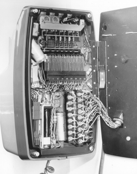
Using Plan-Set N625 Wall
The plan-set is supplied complete with a cord 1400 mm (54 in) and terminal block and three
screws for attachment to the base of the Telephone No. 711 or 741. The two feet must be
removed from the base of the telephone and the three knockouts (two for screws and one for
the interconnecting cord) must be punched out. The interconnecting cord from the plan-set
should be passed through the large hole and the telephone attached to the plan-set by the
three screws. The large spacing washers should be fitted between the telephone and the
plan-set at the upper fixings, but a washer is not required at the lower fixing. Later
models of the plan-set have moulded bosses instead of using spacing washers. The bracket
(Bracket, Telephone, No. 16), which is provided with the telephone, should be fitted on
the wall at the appropriate height and the plan-set attached by engaging the two hooks in
the bracket with the two large holes in the baseplate and fixing with the screw provided.
Assuming that the terminal block is fitted at floor level, the maximum height at which
the apparatus can be fitted is limited by the length of the cord. The keys on the plan-set
should be at a convenient height but the customer should be consulted before the apparatus
is finally fixed. Minimum clearances of 1 ft to the right and 6 in to the left are
required.
In Telephone No. 711 an additional gravity-switch spring-set
(Part No. 1/DSP/1501) and a Capacitor, No. 7712-2 in a Clip No. 90 should be mounted on
the gravity-switch bracket of the main telephone. In Telephone No. 741
a Switch No. 19D-1 and a Kit 166A are used in place of Part 1/DSP/1501.
POWER SUPPLY
The power-unit should be mounted adjacent to a customer provided three-pin socket outlet
which need not be in the same room as the Planset. The power-unit may be fed from a
socket-outlet which is used for other purposes and several power-units may be fed from the
same outlet. Later models of the power unit have four screws for securing the cover, one
in each side face, so that whatever mounting position is chosen for the power unit it is
possible to use at least two screws to secure the cover. The connections from the 10volt
supply to the plan set must not be reversed or damage may occur.
When required, the Converter Ringing, No. 9A (Diagram N626) should be mounted with the relay
uppermost, adjacent to the terminal block.
EXTENSION BUZZER
At internal extensions a suitable buzzer should be fitted to the telephone. This is a
Buzzer No. 32C-1 for Telephones No. 706 or 710, a Buzzer No. 32C-2 for Telephones No. 711
and a Buzzer No. 32C-3 for Telephones No. 740, 741 or 746.
If a Trimphone is fitted a Buzzer No. 20B should be fitted adjacent to the terminal
block.
BELL LOUDNESS
The bell in the Main instrument will be slightly muffled by the plan-set. The bell should
usually be loud enough, but if a customer complains that the bell at the Main cannot be
satisfactorily heard an extension bell may be fitted free of charge.
COMBINATIONS OF EXTENSION PLANS
See TI C3 C0010 for combinations that can include Extension Plans 105, 105A, 107 and 107A.
INTERFERENCE
Noise may be experienced on installations with external extensions routed via underground
cables. This can usually be eliminated by connecting a diode in the earth circuit. Note:
Planphone A already includes this suppression circuit. If this trouble is experienced when
using a Planphone A the details should be submitted on A646 for investigation - see TI Cl
A0050.
Radio interference may occasionally be experienced on installations with external
extensions. This is usually due to the diode in the Converter Ringing, No. 9A. Later
issues have the diode bypassed with a 0.1pf capacitor. Where this is not included by the
manufacturer it should be provided locally.
RECORDS
When the line is tested through to an external extension the current through the test-desk
meter will not be sufficient to operate relay A, thus relay B will remain in series with
the line. The following note should be made in the remarks column on the fault card:-
"The
line resistance to an external extension will be increased by 400 ohms unless a short
circuit is applied between terminals 4 and 5 of the Converter, Ringing, No.
9A"
If ringing is applied directly to the pair connecting an early version of the plan-set
to an external extension, the transistors in the plan-set will be damaged. When an
external extension pair is routed via the exchange the following note should be made in
the remarks space on the fault card for the extension:- 'Transistorised equipment. Do not
apply ringing to this circuit."
CORDS INSTRUMENT
The Plan-Set N625 has hitherto been supplied with a Cord, Instrument, No. 18/04AD... but
latest supplies include a Cord, Instrument, 18/09AD... . This change has been made to
standardise the colour codes used on cordage. The old and new colours are shown in the
relevant diagrams.
An extract from
The Post Office
Electrical Engineers Journal
Volume 57, Part 4 - Dated January 1965
A Wall Mounting Version of the Switching Unit for Use with
700-Type Telephones
Plan-Set N 625 Wall
By K. M. AKESTER
A switching unit is required with 700-type telephones on extension plans with
inter-communication. For table telephones the unit takes the form of a plinth fitted
beneath the telephone. A version of the unit for use with wall-mounting telephones is
described in this article.
INTRODUCTION
Previous articles described the Plan-Set N 625, a switching unit for use with 700-type
telephones on Extension plans with intercommunication. This plan-set is a plinth which is
fitted beneath a Telephone No. 706 or 710. A wall-mounting version has now been produced
for use with the Telephone No. 711, an instrument which offers the facilities of both the
Telephone No. 706 and the Telephone No. 710. The new item has been designated Plan-Set N
625, Wall, and the original item is now known as Plan-Set N 625, Table. Plan-sets
are available in black, grey and ivory.
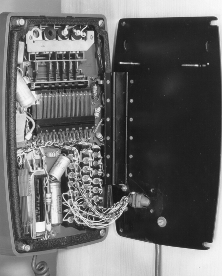
DESCRIPTION
 The wall-mounting version of the Plan-Set N 625 provides the same facilities
as the table version and, as far as possible, uses the same components. In three features,
however, it differs from the table version. The base consists of a framework and
back plate
connected by a double-acting hinge. This is held shut by a spring-loaded catch operated by
a slide bar. To gain access to the plan-set when it is mounted on the wall the slide bar
may be pressed with the blade of a screwdriver and the body slid to the right until two
studs disengage from slots in the edge of the back plate. The plan-set will then swing
open. To close the plan-set the studs are engaged in the baseplate, the body slid to the
left and pressure applied to the hinged end to lock the slide bar. The cord passes through
the back plate and is held by a clamp. It is unusual to provide wall-mounted apparatus with
a cord and terminal block, but this has been done to avoid the necessity of running
several cables up the wall. All keys are of translucent opal Cellulose
Acetate Butyraie (c.a.b.). When the SPK EXTN EXCH HELD and EXTN TO EXCH keys are depressed they
are illuminated by a red lamp and a white lamp, respectively. The wall-mounting version of the Plan-Set N 625 provides the same facilities
as the table version and, as far as possible, uses the same components. In three features,
however, it differs from the table version. The base consists of a framework and
back plate
connected by a double-acting hinge. This is held shut by a spring-loaded catch operated by
a slide bar. To gain access to the plan-set when it is mounted on the wall the slide bar
may be pressed with the blade of a screwdriver and the body slid to the right until two
studs disengage from slots in the edge of the back plate. The plan-set will then swing
open. To close the plan-set the studs are engaged in the baseplate, the body slid to the
left and pressure applied to the hinged end to lock the slide bar. The cord passes through
the back plate and is held by a clamp. It is unusual to provide wall-mounted apparatus with
a cord and terminal block, but this has been done to avoid the necessity of running
several cables up the wall. All keys are of translucent opal Cellulose
Acetate Butyraie (c.a.b.). When the SPK EXTN EXCH HELD and EXTN TO EXCH keys are depressed they
are illuminated by a red lamp and a white lamp, respectively.
CONCLUSIONS
The only apparatus previously available to customers who required a wall-mounting
switching unit for extension plans with intercommunication has been the Bellset No. 20,
which is used with a separate telephone. On most exchange systems the Plan-Set N 625,
Wall, allows the provision of a single wall-mounting unit incorporating 700-type
apparatus. While the majority of customers are likely to require the table version, the
wall-mounting set should prove a useful and popular addition to the range of modern
subscribers' apparatus.
ACKNOWLEDGEMENT
The Plan-Set N 625, Wall, was developed for the Post Office by the General Electric Co.,
Ltd., under the British Telephone Technical Development Committee procedure.

Planset 625 superseded the Bellset No's. 39 &
44, which were used on Plans 5 & 7.
Diagram for 1 extension working - N4509.
Diagram for 2 extension working - N4507.
Diagram for Planset 625 - N625.
Drawing No. 92062.
Diagram for Converter Ringing No. 9 - N626.
GEC Marketing Pictures
Mostly prototypes
|