TELEPHONE No. 746 & 8746 | ||||||||||||||||||||||||||||||||||||||||||||||||||||||||||||||||||||||||||||||||||||||||||||||||||||||||||||||||||||||||||||||||||||||||||||||||||||||||||||||||||||||||||||||||||||||||||||||||||||||||||||||||||||||||||||||||||||||||||||||||||||||||||||||||||||||||||||||||||||||||||||||||||||||||||||||||||||||||||||||||||||||||||||||||||||||||||||||||||||||||||||||||||||||||||||||||||||||||||||||||||||||||||||||||||||
|
Switches for Telephones Model types Telephone No. 8746 - Telephone No. 746 modified for PST working with plug ended line cord General Information on 700 Type Telephones 700 Type telephone circuit description 700 Regulator operation How to wire your Telephone No. 746 to make it work on Plug and Socket How to remove the case Dismantling a Handset No. 3 Restoring the plastic cover and handset Identifying the component parts on the circuit board Click here for the later variant with bell volume control and Unicoil bell Click here to hear a Telephone No. 746 bell ringing Click here for the colour range Colour samples Diagram for Additional Buttons - N849. Diagram for the Auxiliary Switches - N848. Diagram for the telephone circuit diagram - N846, SA 10011 (Telephones No. 746R and 8746) and SA/SAW 102180 (Telephone No. 746C). Specifications - S1404 and S1405. Drawing - 92773, 92773/0/5, 92773/1/1, 92773/1/2, 92773/1/3.
Cut-away picture of a Telephone No. 746 with the later case
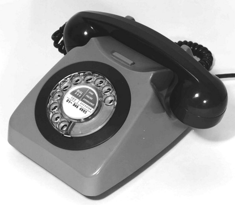
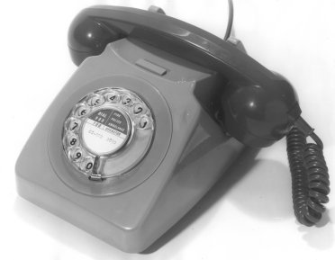
In 1967 the 746 Type telephone was introduced (See also Telephone No. 736). This was an improved version of the 706 range and offered similar facilities. The case styling is slightly different from the Telephone No. 706 although it retains the same overall look. The case now has an integral handle which obviates the need for a separate handle (the Telephone No. 706 plastic handles tended to break). Unlike the Telephone No. 706, this phone could also have two switches fitted. The oblong dummy plate above the dial is removed and a single or two half size transparent plastic buttons could be installed. Originally the case on the "Mark 1" telephone (Part Number 1/DCO/718) had a slope from above the dial, sloping backwards, under the handset, finishing at the raised handset stops to the rear of the case. This design was found to allow the handset to sometimes slide forward and this was sometimes enough to allow the switch hooks to operate - thus leaving the phone off hook. The case was later modified on the "Mark 1A" telephone (Part Number 2/DCO/718) and the handset now rests in a recess, with raised sides to stop the handset sliding forward. The pictures above show both the early and later style cases. Inside the circuit layout is different to the Telephone No.
706 in that the regulator components are soldered directly onto the printed circuit board, the switch-hooks and other components were miniaturised. No conventional wiring version was produced. The same colour options as for the
Telephone No. 706 were offered to the customer. Available to all customers in 1970 and supplied into the late 1980's as maintenance stock. Later phones and refurbished phones had the carbon Transmitter No. 16 replaced by the electronic Transmitter No. 21 (blue or red variants) due to transmitter noise issues.
Telephone No. 746 when used on the Plan 4 system ENGINEERING INSTRUCTIONS TELEPHONES 740 AND 746 General
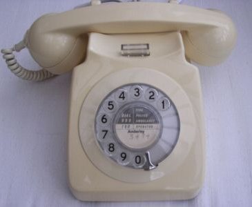
Many parts of the Telephones Nos. 740 and 746 are identical with those of the Telephones Nos. 710 and 706 which are described in A1063 and A1060 respectively. This Instruction describes only those parts particular to the Telephones Nos.740 and 746. The telephones, which as issued are for use in automatic areas only, are suitable for use on lines of up to 1000 ohms T.E.R. The telephones can be modified for a variety of uses by the fitting of add-on units, adapters etc. and these will be described in later instructions. The Telephone No. 746 is available in black, blue, two-tone green, two-tone grey, ivory, red and yellow. The Telephone No. 740 is available in black, two-tone grey and ivory only. Cover The telephones, as issued, have the aperture for the press-button(s) closed with a dummy button held in place by a clip. When a press-button unit is fitted the dummy button and clip should be secured within the telephone for subsequent refitting. A phone with the single switch is shown to the right. The outer dial ring fits round the hole in the sloping face of the cover through which the dial protrudes. The dial ring is secured by dropping the lugs on the ring into the recesses provided on the edge of the hole in the case and turning clockwise until the two recesses provided for the finger-stop line up. To remove or refit the ring the cover must be taken off the telephone assembly. An 'off-rest' position is provided with the handset resting across the instrument just above the dial. A carrying-handle, in the form of a recessed finger ledge, is provided between the horns directly below the normal handset position. Base The plunger-supporting brackets are riveted to the base. Printed wiring board
The printed wiring board is located by mating slots in the front edge of the board and in the sides of the plunger-mounting bracket. The regulator is an integral part of the telephone circuit and provision is not made to render it inoperative. The gravity spring-set consists of a microswitch positioned alongside the left-hand support of the plunger-mounting bracket. The switch is operated by a lever pivoted on a bracket at the rear edge of the switch cover, the upper end of the lever being formed into a channel in which a projection on the plunger assembly rides. A coiled spring holds the lever in position. The switch is operated when the handset is on the rest. When the case is removed the switch can be locked in the off position. The switch hook is manually lowered and the swinging latch arm, which is fixed towards the top of the switch hook mounting, is lifted so that it locates against the front of the arm. Once pressure on the switch hook is removed the latch will be held in place by friction. Pressing the switch Hooks slightly will release the latch. Dial and dial cord Terminal block and line cord Bell Telephone circuit Press-buttons and switches Press-buttons for the Telephone No. 740 are provided by removing the dummy button and fitting a Part 1/ ... 10/DBU/372 using the pin, Part 1/DPI/203, provided in the telephone. A single press-button for the Telephone No. 746 is fitted by removing the dummy button and clip and inserting a Part 1/ or 2/DBU/362 which is retained by two pins, Parts 1/DPI/203. When two press-buttons are required, two Parts 1/ ... 6/DBU/363 are fitted, each with one Part 1/DPI/203. Where a single change-over contact (non-locking) is required in association with a press-button in either telephone a Switch No. 5A-4 together with an operating plunger, Part 1/DPL/1022, is fitted. Other non-locking contact assemblies can be provided on either telephone by fitting the spring-sets described in Diagram N848 together with a Part 1/DPL/1022. Where a locking single change-over contact is required in association with a, press-button on either telephone a Switch No. 5A-9 is fitted (this switch includes an operating plunger and is now superseded by Switch No. 23A). Other locking contact assemblies can be provided on the Telephone No. 740 by means of the latch-plate as described in A1063 and Diagram N848. Additional gravity switches can be fitted to either telephone when required as follows:-
Additional fittings Replacement parts TABLE 1 Part To be requisitioned as:-
References:- A1060 & A1063 How to remove a Telephone No. 746 or 740 case
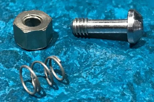
Re-fitting is the process in reverse, except you may have to slide the casing dial ring about to locate it over the dial. If the casing screw does fall out - fit back as follows:-
Additional information
The Telephone No. 8746 can be found in C, D, F, G, GR and R variants. The GR and R variants were fitted with Earth recall switches. All these models date from 1981 onwards. Specification - S1481. Every variant was available in the seven standard colours except for the F and G variants which were also available in Brown. The Telephone No. 8746C still retained the 1000 ohm bell but was fitted with a Telephone Unit D94244. Telephone No. 8746D was fitted with a 4000 ohm bell and the Telephone Unit D94244. Telephone No. 8746F has a Bell 59C-1 (1000 Ohm D.C. Resistance).Telephone No. 8746G has a Bell 59D-1 (4000 Ohm D.C. Resistance). New Zealand used this telephone and called it the Telephone No. 101.
Telephone SA 4284 Telephone SA 4284 is a Telephone No. 746 used for Teleprax working. The Telephone No. 746F is modified for buzzer calling and 6v working.
Additional Pictures
This is the brown - Yeoman Telephone No. 8746
Telephone No. 746 in brown - Yeoman (late 1970's)
|
||||||||||||||||||||||||||||||||||||||||||||||||||||||||||||||||||||||||||||||||||||||||||||||||||||||||||||||||||||||||||||||||||||||||||||||||||||||||||||||||||||||||||||||||||||||||||||||||||||||||||||||||||||||||||||||||||||||||||||||||||||||||||||||||||||||||||||||||||||||||||||||||||||||||||||||||||||||||||||||||||||||||||||||||||||||||||||||||||||||||||||||||||||||||||||||||||||||||||||||||||||||||||||||||||||
Last revised: July 15, 2026FM |


 On both types of telephone the cover is secured to the telephone assembly by a lug on the front skirt which engages in a recess in the leading edge of the base and by a single fixing screw located above the cord entry at the rear of the case. The screw, which is held captive by a bush and a spring, engages in a tapped hole in the cord clamp, a T-shaped metal bracket riveted to the rear of the base.