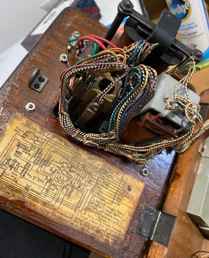
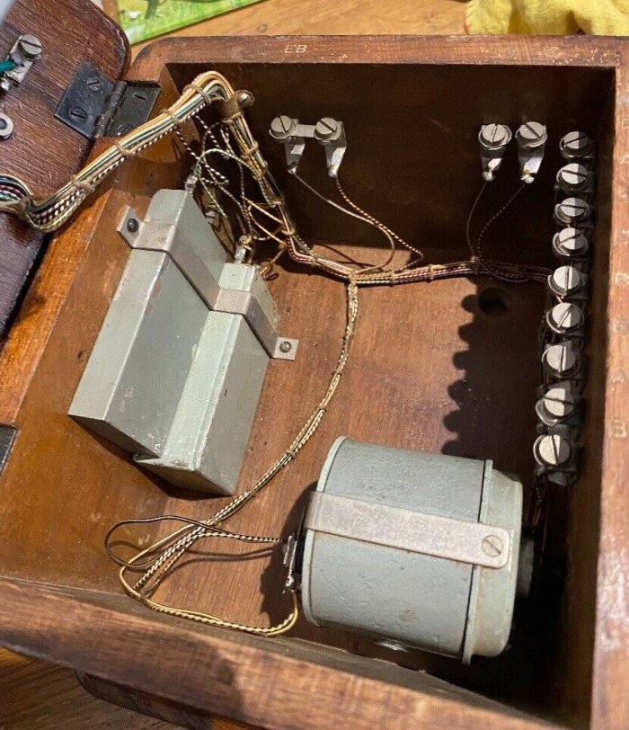
BELLSET No. 20 | ||||||||||||||||||||||||||||||
 Wooden Bellset for use with table or wall telephones on an Extension Plan No. 5, 5A, 7 or 7A. These Extension Plans consisted of one exchange line and one extension with intercommunication, or one exchange line and two extensions with limited intercommunication. This Bellset replaced the Bellset No. 4 and gave superior transmission quality. The Bellset could also provide secrecy when the extension was connected to the exchange line. This required the removal of links fitted between the A - A1 and B - B1 terminals. An extension bell could be wired to terminals E B after removal of the wire link. The Bellset is provided at the main station and batteries provided for internal communication. There were three Cells, Dry R40 supplied and these were located in a Box, Battery No. 2, which was fitted close to the Bellset. Introduced in 1925 (date on initial GPO diagram) and also found in the GPO 1928 to 1971 Rate Books. Used as follows (1928 Rate Book):-
Used as follows (1944 and 1956 Rate Books):- There were numerous variants called Mark 234, Mark 235, Mark 3 (1945) and Mark 4 (1952). The Mark 4 had a new style terminal strip fitted at the base of the Bellset and much of this was remedial work done by the GPO Holloway Factory. Bellset No. 20 Mark 234 includes (1928):- Bellset No. 20 Marks 235, 3 and 4 includes (1946 and 1956):- The Indicator and Key No. 12 consists of a Key No. 248 and an Indicator No. 3800A, mounted on a plate. Supersedes Bellsets No. 4 and No. 13. Superseded by the Bellset No. 39 Produced by GEC, their Catalogue List No. 871. Circuit diagram - N520. Drawing - 8581/1 (Mark 3) and
8581/2 (Mark 4). Specification - S51. Diagram for 1 extension working (Plan 7) - N4310 Diagram for 2 extension working (Plan 5) - N4308
Connecting to the UK telephone system Click here for the difference between a Bell and a Bellset Additional Information This BPO wooden bell set was originally introduced to replace Bell Set No. 4 on Plan No's 5, 5A, 7 and 7A installations connected to automatic exchanges. The Bellset is shown to the right and the picture is dated 1932. As it was found to give better transmission conditions than Bell Set No. 4, its use was extended to Central Battery manual circuits. The Bell Set consists of a 4-position switch, an indicator-relay (Relay 257A of 50 ohms resistance), a Generator No. 4C, a Bell No. 1A, a 2uF condenser, and a 1uF condenser. A two-cell battery is provided to furnish speaking current on main to extension calls. The connections of the telephones resulting in the four positions of the switch are similar to those of the Bell Set No. 4. The internal connections of the Bell Set No. 20 are shown in diagram N520. It will be seen that the indicator relay is shunted by a 2uF condenser instead of by a non-inductive resistance as in the Bell Set No. 4. Also the magneto bell of the main telephone is disconnected by the contact of the indicator relay when the switch is in the through position. By these means, a circuit clear of any bridged apparatus is provided, with the result that, under automatic conditions, there is no distortion of the dialled impulses on account of the introduction of the bell set. The generator used at the extension instrument is connected in series with a 2 uF condenser, this combination being known as Generator No. 4CP. The necessity for the condenser arises from the fact that should the generator handle be turned when the switch is in the through position, the indicator relay would be operated by the current flowing round the loop provided by the armature of the generator when brought into circuit by the operation of the cut-out spring, whereas it is necessary that this relay should be released in order to connect the magneto bell at the main for the reception of the ring. The indicator-relay is of the pendant armature type, and is provided with a copper sleeve on the core. The armature actuates a single change-over spring set and an indicator attachment, consisting of a balanced aluminium lever which moves an aluminium flag into position behind a rectangular window. The indicator relay was designed by Messrs. Siemens Brothers to meet the following conditions:-
The switch is a GEC design.
Bellset No. 20 (Mark 234) Taken from "Telephony - a detailed exposition of the telephone system of the British
Post Office - volume 1 - manual switching systems and line plant" Additional Pictures
|
||||||||||||||||||||||||||||||
Last revised: June 20, 2025FM |