|

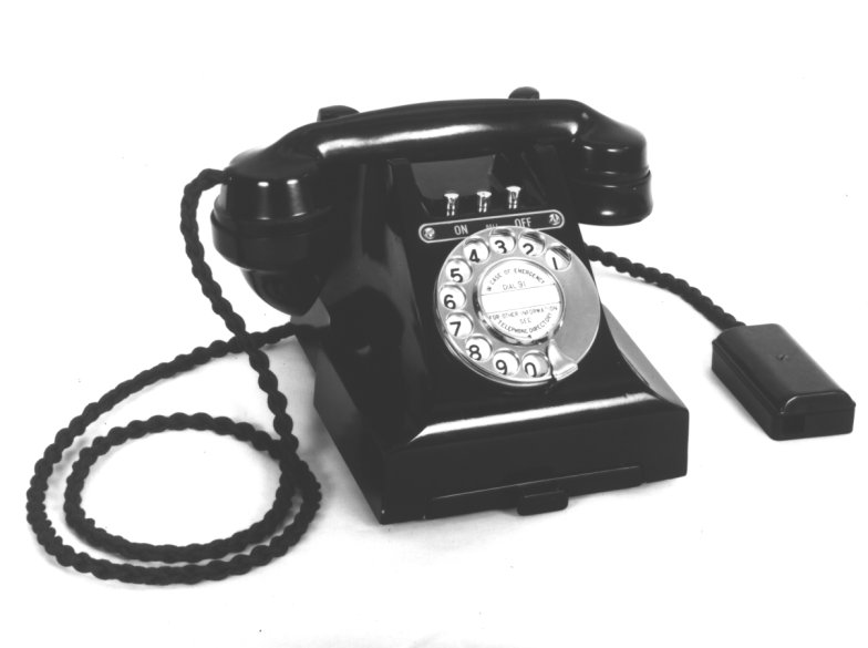
Combined table handset telephone, introduced in 1937, for use
in C.B. and Automatic
exchange areas. This telephone had a tray for the
subscribers personal directory but as from June 1940 the tray
was not fitted and instead the telephone was supplied with a
Tray, Dummy, D62099 (a blank plate). This was probably a
war time cost saving, as in late 1947 the tray was
re-introduced.
The telephone only has a DC trembler bell
ringer with one bell gong.
There is provision in the case for three additional keys/press buttons.
The handset is a Telephone
No. 164.
The telephone was used on extension plans that
required extra switches on the telephone and a DC bell for
internal signalling.
Mark 1 - has a Receiver, Inset No. 1L in the handset and
hook switch mechanism with plungers of the early type.
Mark 1A - has a Receiver, Inset No. 1L in the handset and hook
switch mechanism with
plungers of an improved type.
Mark 2 - has a Receiver, Inset No. 2P in the handset and hook
switch mechanism with plungers of the early type.
Mark 2A - has a Receiver, Inset No. 2P in the handset and
hook switch mechanism with
plungers of an improved design.
Telephone includes (1946):-
1 x Bell No. 65A, Unmounted.
1 x Part No. 3/SCA/17, Black.
1 x Bell-gong No.2, Nickelled.
1 x Capacitor, M.C. No. 97.
1 x Telephone No. 164, Black.
1 x Coil, Induction No. 27.
1 x Tray, D 62076, Black or Tray, D1/62833, Black or Tray,
Dummy, D62099, Black.
1 x Dial, Automatic, Dummy No.3, Black (on CB variant).
1 x Filter, Suppression No. 26A.
To be requisitioned separately as required:-
1 x Block, Terminal No. 20/ . . , Black.
1 x Cord, Instrument No. 5/28E, 5".
1 x Dial, Automatic S.S., No. 10 . . .
1 x Key No. 303A or 304A.
1 x Label No. 160.
1 x Label No. 252 ..., Black.
If another colour other than black was required then all the
black parts would be replaced with the required coloured parts.
British Ericsson provided the GPO with Telephone No. 326CB,
their model
N1366 and N1071L1.
Circuit diagram - N426.
Diagram for Button labels - N620.
Drawing No. 63022 - Telephone
components parts.
Drawing No. 63023 - Chassis components.
Drawing No. 63250 - Chassis
components (improved switch hook buttons).
Drawing No. 90319 - Telephone
parts (Mark 3A).
Drawing No. 90373 - Chassis
components (improved switch hook buttons).
Drawing No. SBA12
- 300 type base plate.
Drawing No. 3/SCA17 - 300 type
complete case.
Drawing No. 3/SCA20 - 300 type
case.
Drawing No. 3/SCA47 - 300 type
complete case (improved switch hook buttons).
How to wire your Telephone No. 326
to make it work on Plug and Socket
300 Type
telephone circuit description
Dismantling your Telephone No. 326
Dismantling the Handset
History, Technical and General
Information on 300 type telephones
Collectors information
Adjustment of the Bell No. 65A
Keys for use in 300 type wall and table
telephones
Lamp Fittings
Labels that fit in the sliding tray
General fault finding on your phone
How to restore Bakelite
Comparison chart of GPO 300 type
telephones

The picture above shows the inside of a
Telephone No. 326
Note: Only one bell gong and the bell ringer is a DC
trembler mechanism
In place of the missing bell is an anti-sparking circuit for the
bell contact breaker

Typical 300 type chassis showing dial cord wiring arrangement

Telephone No. 326 chassis
Induction to the left, Bell No, 65A in the centre and the
capacitor to the right
Lower right is the radio interference suppressor for the bell

|