TELEPHONE No. 321 |
|||||||
|
These were used by the BPO on shared service lines and extension plans, where a wall telephone was required. Produced in Automatic or C.B. variants. The C.B. variant was fitted with a Dial, Automatic, Dummy No. 3. The handset is a Telephone No. 164. The case and all internal components are mounted on a plate. This plate is fixed to the wall, by means of 4 rubber mounts, using wood screws. The case was fixed by a single screw next to the handset cord entry. The case had a strap that was fixed to the telephone back plate allowing the case to hang during maintenance work. It is fitted with an AC bell ringer and has provision for three press button. It was supplied fitted with a single press button plunger but had no switch units fitted. A switch unit would be fitted locally, the type dependent on the installation. Produced in the colours; Black, Chinese Red, Ivory and Jade Green. To remove the case, release the lower fixing screw adjacent to the handset cord entry point. Pull the bottom of the case outwards about one inch. Lift the case upwards to release the top fixings. The telephone has provision for three press buttons and can be used with Adaptors Shared Service No. 1 & 2. It is the wall equivalent of Telephone No's 312, 314, 328 and 330. The model with no press buttons was the Telephone No. 333. Telephone No. 321F supplied by British Ericsson as their Model No. N1075. Telephone No. 321CB supplied by British Ericsson as their Model No. N1423A1. Telephone Includes (1955):- The case is a Part 1/DCA/89 (ETL part N82536). Circuit diagram - N421. Diagram for Button labels - N620. Drawing - 90509. Specification - S77. How to wire your Telephone No. 321
to make it work on Plug and Socket
Case removed
Case removed and showing an Adapter Shared-Service No. 1 (centre)
Internal view showing a Key No. 303A installed
Rear view showing fixing lugs
|
|||||||
Last revised: August 21, 2025FM |
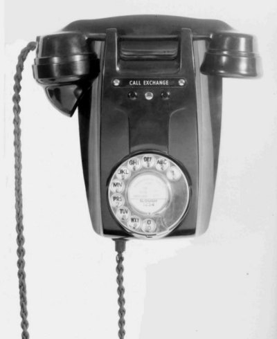 This Bakelite
cased wall
telephone was introduced in 1955.
This Bakelite
cased wall
telephone was introduced in 1955.


