Click here for Power Unit TL2529
Click here for mains operated Ringing GeneratorsTELECOMMUNICATIONS INSTRUCTION
C MARKETING INSTALLATION
3 Internal
Q0020
Issue 2, Nov 1977
POWER-UNITS Nos. 50A, 51A, 52A, 53A/B, 55A, 56A, 57A, 62A,
69A, 70A, 73A & B, 77A, 78A, 86B, 88A, 100A/1, 100A/2 AND 100A/4
GENERAL
 These
power units are for converting single phase 50 Hz mains supplies in the range 220-250
volts into d.c. suitable for operation of telephone apparatus at subscribers premises. The
outputs are smoothed sufficiently for their intended uses. These
power units are for converting single phase 50 Hz mains supplies in the range 220-250
volts into d.c. suitable for operation of telephone apparatus at subscribers premises. The
outputs are smoothed sufficiently for their intended uses.
There is no provision for an alarm being given in the event of failure of a unit or of the
mains supply.
The output voltages quoted are for nominal values of input mains supply voltages.
The units are metal cased and finished in eggshell elephant grey except for:-
(i) Some early units which are finished in battleship grey.
(ii) The Power Unit
No. 70A which has a light straw finish metal cover.
(iii) The Power Unit No. 53A MK2 which has an eggshell elephant grey plastic cover.
Space and fixings for mounting a Converter, Ringing, No. 7 are provided in Power Units Nos.
50A, 51A, 52A, 55A, 56A, 57A and 62A (see Q0006 for mounting details).
Space and fixings for mounting a Transformer
No. 261A are provided in Power Units Nos. 52A
and 62A.
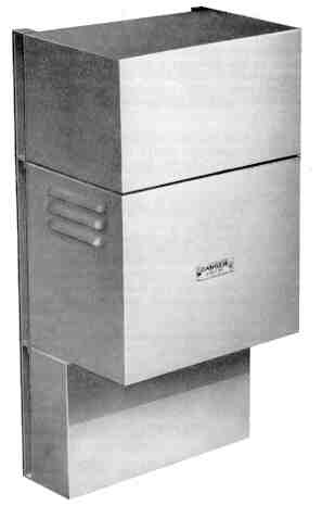
Power Unit No. 51A is shown to the right (the picture shows a setup at a
PMBX No. 2/. installation where the lower box is the distribution case and
the top box a Unit Auxiliary Apparatus).
CONDITIONS OF USE
Power units must not be used at installations serving emergency services, e.g. Civil
Defence, police, fire stations, ambulance centres or hospitals without first inquiring
whether standby battery-power to carry on full extension-to-extension service during mains
failures is needed. Similarly these units must not be used to serve Police Telephone and
Signal Systems or House Exchange Systems other than the House Exchange Systems Nos. 3 and
4 because,' under mains failure conditions. these systems are rendered completely
inoperative. When Switchboards, AT 3796... and N 1070... are to be served by a power unit,
they must be modified to Dgm N 1099 which, under mains failure conditions, makes the
operators headset independent of the power-unit supply on exchange calls.
MAINS FAILURE CONDITIONS
When the a.c. mains supply fails at any installations listed below served by a power unit
the following conditions will obtain:-
At PMBX Installations
(a) Extension-to-exchange calls in progress will remain held.
(b) The operator can make and answer exchange calls.
(c) Extension-to-exchange calls can be made and answered using the normal night service
facilities.
(d) The making of extension-to-extension calls will not be possible and any in progress
will fail.
(e) Operator-to-extension or extension-to-operator calls will not be possible.
(f) Inter-switchboard circuits and number-wheel-type subscribers private meters will be
inoperative.
At PABX No. 5 and No. 6 Installations
All calls in progress are lost.
Exchange lines are diverted to predetermined extensions which can then make and receive
exchange calls. When the mains supply is restored any such calls in progress are
maintained.
MISCELLANEOUS INSTALLATIONS
Plan-set N 625
Intercommunication facilities are lost, but exchange calls may still be made and answered
at all instruments.
House Exchange Systems
On House Exchange System No. 3 calls between stations will be lost but exchange calls may
be made and answered at all stations. The same conditions apply on House Exchange System
No. 4 but, additionally, exchange calls may be lost at non-multiplied stations.
Amplifier and Loudspeaker No. 4
Loudspeaking Telephone No. 4 and Confraphone Amplifying facilities are lost.
House Telephone System
All facilities lost.
Key and Lamp Units No. 2A and 10A
(a) Visual signals and alarms for incoming calls will be inoperative.
(b) Exchange line or PBX extension line calls in progress will remain held.
(c) Outgoing exchange line or PBX extension line calls can be made.
(d) Private circuit calls will not be possible.
INSTALLATION
The subscriber must provide a standard 3 pin BS wall socket adjacent to the wall mounting
position of the unit, supply electrical energy free of charge to the PO and provide an
efficient mains earth connection. For the connection of the mains supply to any of these
power units the PO will supply a suitable plug and flexible cord. If one pole of the power
unit output is to be connected to a telephone signalling earth a strap must be provided at
the power unit terminal block linking the telephone signalling earth to the mains
protective earth. The earth conductors must not be less than 1.5 sq. mm i.e. Cord Flexible
3183Y 1.5mm from the mains plug to the power unit and Wire Earthing 9141/lW or 9142/1W for
the strap and telephone signalling earth. The telephone signalling earth should be in
accordance with TI A2 E1006, the preferred method being by connection to the Consumers
Earthing terminal provided by the Electricity Board unless the electricity supply is by
overhead distribution. The signalling earth lead must not be connected to the power supply
earthing system at the socket outlet but must be independent of the Consumer's earth
continuity wiring.
When Plugs, for Socket-Outlets No. 102 are used they shall be fitted with Fuses Plug for
Socket Outlets No. 102/13 for the Power Unit Nos. 70A, 77A and 78A and Fuses Plug for
Socket Outlets No. 102/3 for all other power units listed below.
When 3 pin/5 Amp plugs are used, the socket outlet must be protected at a distribution
board by a fuse, or similar protective apparatus, rated at not more than 5 Amp. When only
a 15 Amp 3 pin socket-outlet is available an adapter should be purchased locally and
fitted to permit the use of a single Plug, for Socket Outlet No. 102 fitted with the
appropriate fuse.
All power units are to be connected to the mains socket outlet plug with Cord Flexible
3183y 1.5mm except the Power Units Nos. 53A and B which, as neither pole of their outputs
is to be earthed, are connected with Cord Flexible 3183Y 0.75mm.
MOUNTING ARRANGEMENTS
Power Unit No. 53B is intended for wall mounting, using Screws, for Wood........ Size 6.
Power Units Nos. 53A, 73A, 73B, 86B and 88A are intended for wall-mounting, using Screws,
for Wood....... Size 8.
Power Units Nos. 50A, 51A, 52A, 55A, 56A, 57A, 62A, 77A and 100A/.. are intended for wall
mounting, using Screws for Wood .... Size 10 and are fitted with brackets for this
purpose.
Power Units Nos. 69A and 70A are fitted inside the PABX cabinets.
Power Units Nos. 50A, 51A, 52A, 62A and 100A/.. conform to the general appearance and
mounting arrangements of the auxiliary apparatus unit used with Switchboards, PMBX
No. 2/... and PMBX No. 4/1A. All units are mounted one above the other in the same vertical
wall assembly, the power unit being placed near the bottom and immediately above the
connection box to ensure adequate ventilation. The connection box, power unit and
auxiliary units are fixed together (using ORA nuts and bolts provided with the connection
box and the auxiliary unit) to form a complete assembly which should be attached to the
wall with as many fixing points as are necessary.

Power Unit No. 50A complete with Converter Ringing No.
7 (fitted to the front left)
Power Units No. 77A is similar in appearance to Power Units Nos. 50A, 51A, 52A, 62A and
100A/.. but should be mounted clear of other apparatus to allow a free circulation of air.
Power Unit No. 78A is intended to stand on the floor.
SELECTION OF APPROPRIATE POWER UNIT FOR STANDARD INSTALLATIONS
A guide to the selection of the appropriate power unit for a particular installation is
given below.
The Power Units Nos. 100A/.. contain an integral ringing converter which will ring up to
four series connected Bells No. 59A in series with a 2PF capacitor.
The Power Units Nos. 53A and 53B are electrically interchangeable but the latter is
physically smaller.

Power Unit No. 53A

Power Unit 86B
Used on the LST No. 4
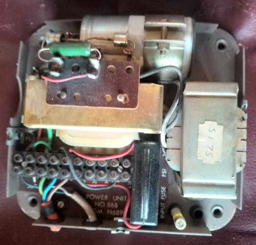
Power Unit 86B
Power Unit Uses
| Apparatus |
Power Unit (PU) No. |
| Amplifier and Loudspeaker No. 4 |
PU No. 73B |
| Autodial No. 101A |
PU No. 88A |
| Planset N625 |
PU No. 53A or 53B |
| HES No. 3 |
PU No. 100A/1 |
| HES No. 4 |
PU No. 100A/2 |
| HTS |
PU No. 53A or 53B |
| Key & Lamp No's 2A and 10A |
PU No. 52A |
| LST No. 4 |
PU No. 86B |
| PABX No. 5 |
PU No. 69A |
| PABX No. 6 |
PU No. 70A |
| PMBX No. 2/2 |
PU No. 100A/1 |
| PMBX No. 2/3 |
PU No. 100A/2 |
| PMBX No. 2/4 (without aux apps) |
PU No. 100A/2 |
| PMBX No. 2/4 (with aux apps) |
PU No. 100A/4 |
| PMBX No. 3/5 |
PU No. 100A/4 |
| PMBX No. 4 (up to 4 amps) |
PU No. 62A |
| PMBX No. 4 (up to 8 amps) |
PU No. 77A |
| PMBX No. 4 (up to 12 amps) |
PU No. 78A |
| Switchboard CB 873 |
PU No. 56A |
| Switchboard 10 + 30 |
PU No. 56A |
| Switchboard 10 + 50 |
PU No. 57A |
Additional Information
| Power Unit Number |
Output Current |
Output Voltage (DC) |
Diagram |
| No. 43A |
2A |
50v |
N639 |
| No. 50A |
0.5A |
50v |
N635 |
| No. 51A |
1A |
50v |
N636 |
| No. 52A |
2A |
50v |
N637 |
| No. 53A |
0.25A |
10v |
N631 |
| No. 55A |
0.3A |
25v |
N667 |
| No. 56A |
1A |
25v |
N668 |
| No. 57A |
2A |
25v |
N669 |
| No. 62A |
4A |
50v |
N670 |
| No. 69A |
4A |
50v |
N672 |
| No. 70A |
5A |
50v |
N673 |
| No. 73A |
1A |
12v |
N674 |
| No. 77A |
8A |
50v |
N684 |
| No. 78A |
12A |
50v |
N685 |
| No. 86A |
0.275A |
50v |
N689 |
| No. 88A |
1A |
18v |
N688 |
| No. 100A/1 |
1A |
50v |
N700 |
| No. 100A/2 |
2A |
50v |
N700 |
| No. 100A/4 |
4A |
50v |
N700 |
Power Units 100A/.. are equivalent to Power Units 51A, 52A and
62A except the 100A/.. has a Ringing Convertor factory fitted.
WARNING
When working on power units always switch the mains off and
isolate the supply (pull out the plug). Even with the input isolated, capacitors
within the unit will take a time to discharge - do not work on the unit for at least 5
minutes.
On most modern GPO power units, the smoothing capacitor had a
resistor wired across it to discharge it when the mains is switched off. Whilst
preventing possible electric shock to those working on the PSU the resistor will remain
hot for a long period of time, thus providing the possibility of burns.
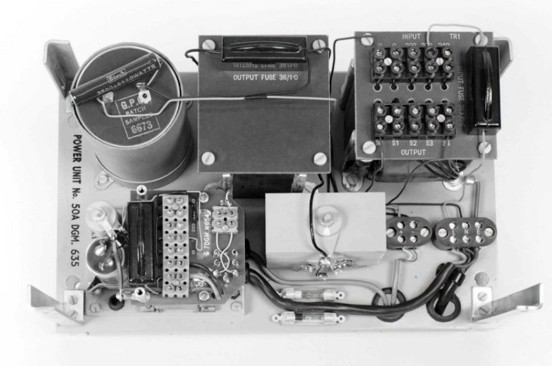
Power Unit No. 50A with Converter, Ringing No. 7
installed
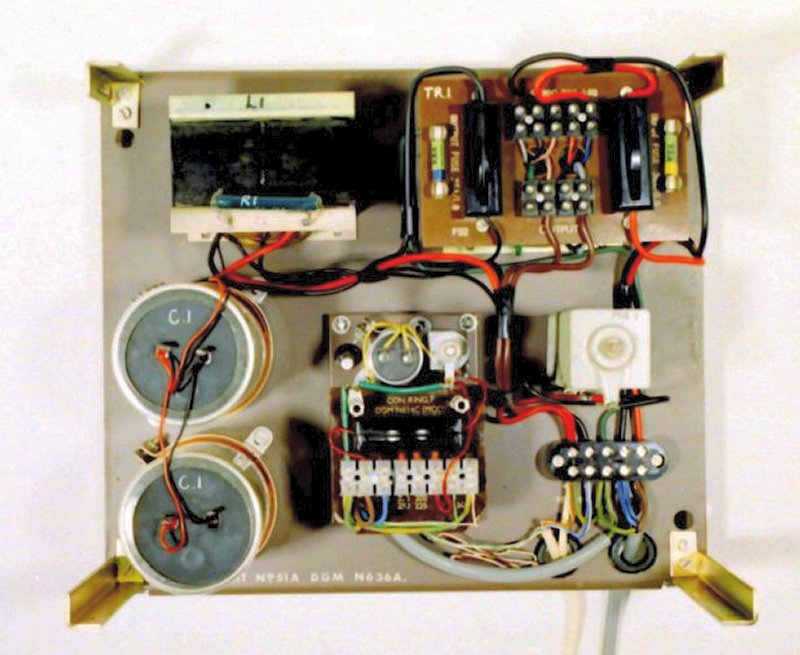
Power Unit No. 51A with Converter, Ringing No. 7 installed
|